b. Applicability:
Below are different riding positions to child restraint system

This manual will familiarize you with the operation and maintenance of your new vehicle. It will also provide you important safety information. Please do read it carefully and follow the recommendations. This manual is like a permanent part of your car. It would go a long way in ensuring a safe and trouble-free operation and running of your JSW MG Astor.
In case of any query, please feel free to call our 24 hours Helpline at 1800 100 6464 or email us at: pulsehub@mgmotor.co.in
Find your nearest JSW MG authorized dealer by visiting www.mgmotor.co.in/tools/dealersSAFE and HAPPY DRIVING
From
Team JSW MG India


This handbook describes all of the vehicles and standard equipment specification within the model range. Some of the information therefore, may not apply to your particular car.
Always remember that if you have any queries concerning the operation or specification of your car, your JSW MG Authorised Service Centre will be glad to advise you.
The illustrations in the Owner's Handbook are for reference only
The information presented in this manual may vary slightly depending on vehicle configuration, software version and sales area.
JSW MG operates a policy of constant product improvement and therefore, reserves the right to change specifications without notice at any time. Whilst every eort is made to ensure complete accuracy of the information in this publication, no liabilities for inaccuracies or the consequences thereof, including loss or damage to property, or injury to persons, can be accepted by the manufacturer or JSW MG Authorised Service Centre who supplied the publication, except in respect of personal injury caused by the negligence of the manufacturer or JSW MG Authorised Service Centre.
The following symbols used within the handbook call your attention to specific types of information


This symbol indicates parts described must be disposed of by authorised persons or bodies to protect the environment.
AsteriskAn asterisk (*) appearing within the text, identifies features or items of equipment that are either optional, or are only fitted to some vehicles in the model range.
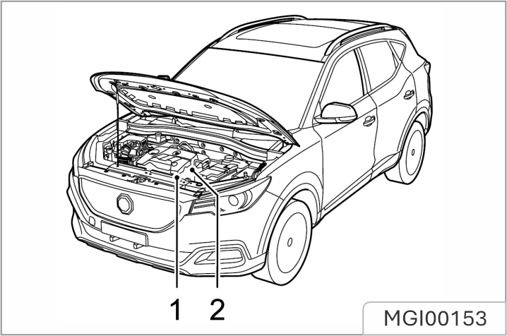
1. Engine Number
2. Transmission Number
Always quote the Vehicle Identification Number (VIN) when communicating with your JSW MG Authorised Service Center. If the engine or transmission is involved, it may be required to provide the identification numbers of these assemblies.
Vehicle Identification Number (VIN)
Stamped on the front right of the cylinder block (View from the front of the engine).
On the surface of the transmission housing in the engine compartment. The transmission numbers of certain models are only visible by raising the vehicle, please contact a local Authorised Repairer.
The vehicle identification label contains the following information:
Location of Vehicle Identification Label
The identification label is located at the lower side of right pillar B
This section of the manual, along with others, contains crucial safety guidelines. Please pay special attention to the following precautions:
a. Always use your seat belt: It provides the best protection in any type of accident. Airbags are designed to complement seat belts, not to replace them. Therefore, even though your vehicle has airbags, ALWAYS ensure that you and your passengers wear your seat belts and wear them correctly.
b. Secure all children: All children under the age of 13 should ride in the back seat of your vehicle, properly restrained. Infants and small children should be secured in an appropriate Child Restraint System. Older children should use a booster seat with a lap/shoulder belt until they can safely use the seat belt alone, without the booster seat.
Adjusting the seats so that you are sitting in a safe and comfortable position plays an important role for the safety of the driver and passengers, as much as seat belts and air bags when in an accident.
Do not use a cushion that reduces friction between the seat and the passenger. The passenger's hips may slide under the lap portion of the seat belt during an accident or a sudden stop. Serious or fatal internal injuries could result because the seat belt cannot operate properly.
c. Safety precautions: Adjusting the seats so that you are sitting in a safe and comfortable position plays an important role for the safety of the driver and passengers, as much as seat belts and air bags when in an accident.
d. Airbag risks: Though airbags can be life-saving, they can also cause serious or fatal injuries to those who are too close or not properly restrained. Infants, young children, and shorter adults are especially at risk. Adhere to all instructions and warnings provided in this manual regarding airbags.
e. Avoid driver distraction: Driver distraction is a significant and potentially fatal hazard, particularly for inexperienced drivers. Always prioritize safety and be aware of distractions like drowsiness, reaching for objects, eating, grooming, interacting with other passengers, and using mobile phones. To minimize distraction:
f. Maintain appropriate speed: Driving at excessive speeds is a leading cause of accidents and injuries. Higher speeds increase the risk of severe consequences, although serious injuries can also occur at lower speeds. Always drive at a safe speed for the current conditions, regardless of posted speed limits.
g. Ensure vehicle safety: Tire blowouts or mechanical failures can be dangerous. To minimize these risks, regularly check your tire pressures and conditions, and follow all scheduled maintenance guidelines.
a. Front seat position:
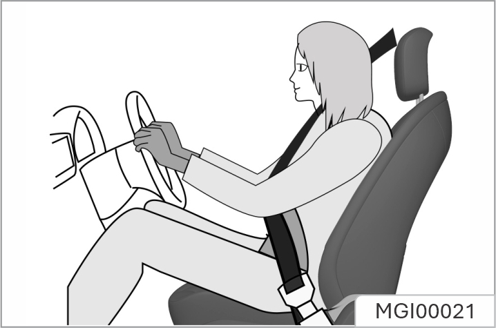
When you sit on the seat, make your hip as close to the backrest as possible. Adjust the distance between the seat and the pedal to make your leg slightly bend when you press the pedal. The passenger’s seat shall slide as backward as possible.
Make your shoulders lean on the backrest as backward as possible. Set the backrest inclination angle to make your arm conveniently to reach the steering wheel while slightly bending the arm. Keep the shoulders leaning against the backrest while turning the steering wheel. The backrest shall not incline excessively backward. We suggest that the inclination angle of all backrests shall not be more than 25 degrees.
The seat height shall be so set that the occupant can see all directions and the positions of all display instruments. The head must be at least one hand away from the roof lining. The thighs are right on the seat without constriction.
When adjusting your seat, follow these precautions:
The power seats can be moved even when the vehicle is turned off.
To avoid damaging the seats:
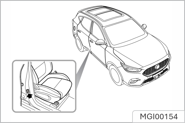
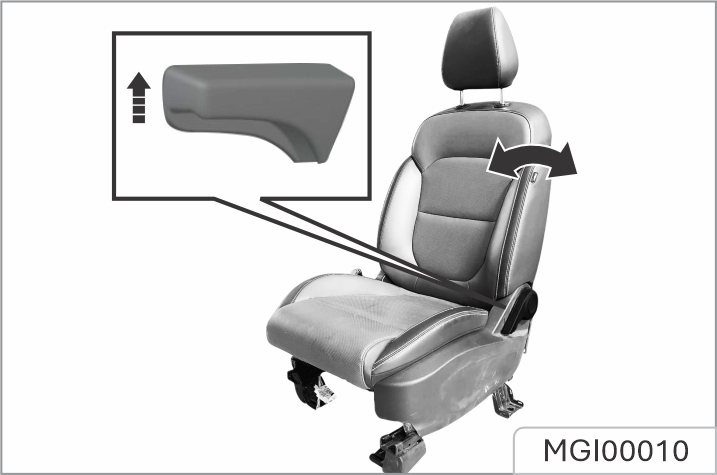
b. Seat position adjustment :
Electric adjustment type*
As shown in the figure, the electric adjustment switch is on the outer side of the seat. Push the switch forward or backward, and the seat will move forward or backward accordingly. Release the switch when it reaches a proper position.
If the seat does not move when the switch is turned, the seat may be already at its limit position, or the vehicle battery runs out. Please check for confirmation. Never turn the switch forcibly to avoid any damage.
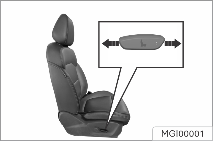
Manual adjustment type*: You can adjust the front seat by using the levers located under the seat cushion.
Before you start driving, adjust the seat to the right position so that you can comfortably reach the steering wheel, foot pedals, and controls on the dashboard.
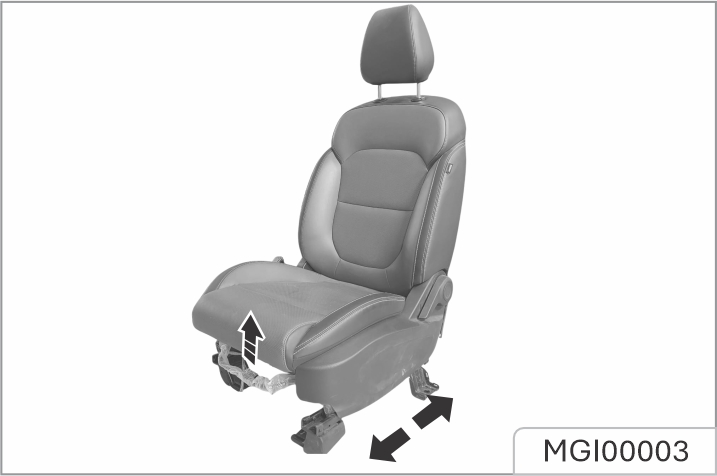
To adjust the seat forward or backward, pull upward the adjustment lever on the front lower part of the seat to adjust the seat forward or backward, and release the lever after the seat is adjusted to a proper position.
Try to slide the seat forward and backward to ensure that the seat is locked at a proper position.
c. Seat backrest adjustment
Electric adjustment type*
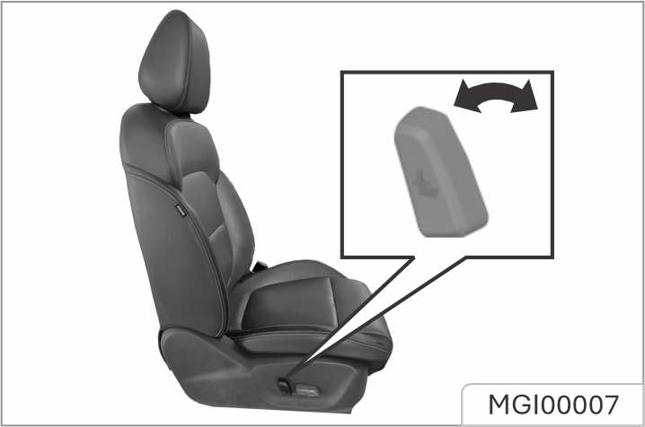
As shown in the figure, turn the adjustment switch forward and backward, and the backrest will be folded forward or unfolded backward depending on the vehicle configuration. Release the switch when it is adjusted to a proper position.
If the backrest does not move when the switch is turned, the backrest may be already at its limit position, or the vehicle battery runs out. Please check for confirmation. Never turn the switch forcibly to avoid any damage.
Manual adjustment type*:
Pull up the handle near the seat cushion; adjust the backrest inclination angle to a proper position; then, release the handle.
After adjusting the seat backrest, try to shake the backrest to ensure that the backrest is locked.
The backrest plays an important protection role when the vehicle is running. Unlocked backrest may cause severe personal injuries in case of sudden braking or a collision. Any time after adjusting the seat backrest, shake the backrest to check whether it is locked even though no passenger occupies the seat.
Reclining the seatback: Sitting in a reclined position while the vehicle is moving can be dangerous. Even if you're wearing your seat belt, reclining the seatback reduces the eectiveness of your seat belt and airbags.
Never recline the seatback while the vehicle is in motion. Riding with a reclined seatback increases the risk of serious or fatal injuries in a crash or sudden stop. Drivers and passengers should always sit upright in their seats, properly restrained, with the seatbacks upright.
Seat belts need to fit tightly across your hips and chest to work correctly. When the seatback is reclined, the shoulder belt cannot properly secure your chest-it may sit in front of you instead. In an accident, this could cause you to be thrown into the seat belt, potentially causing neck or other injuries.
The more the seatback is reclined, the higher the risk that the passenger's hips could slide under the lap belt or the passenger's neck could hit the shoulder belt.
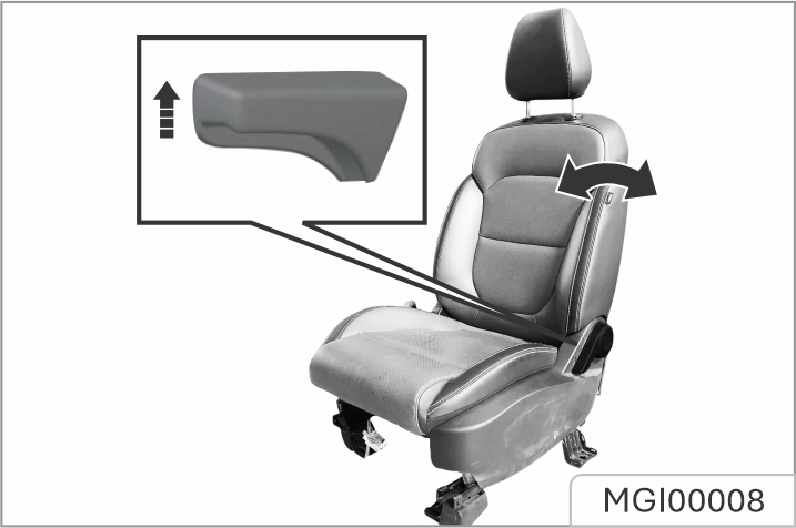
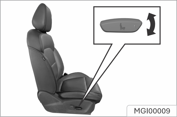
d. Seat height adjustment:
Electric adjustment*
As shown in the figure, rotate the height adjustment switch on the outer side of the seat cushion, and then release the switch after the seat is adjusted to proper height.
Manual adjustment*
Turn the handle on the outer side of the seat upward and downward until the seat is adjusted to the desired height. While adjusting the seat height, the seat must be loaded.
Therefore, please sit on the seat before adjustment; otherwise the adjustment device may be damaged.
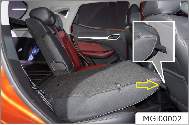
Folding Rear Seats
To increase luggage space, first fully lower (or remove) all the rear seat head restraints, and then pull up the backrest unlock straps on both sides respectively and fold the seat backrests forward.
When the head restraint of the rear seat is not fully lowered or the backrest of the front seat is inclined backward excessively, the folding of the rear seat is very likely to damage the back of the front seat, small storage compartment or head restraint of the rear seat.
Unfolding and Locking Rear Seat Backrests
When returning the rear seat backrest to the upright position, pull up the backrest unlock straps to release the locked state, push the backrest until it reaches an appropriate position, and the backrest is locked when you hear a click.
When returning the rear seat backrest to the desired position, make sure that the rear seat belt is not trapped.
Front Seat ventilation*
The seat ventilation switch is located in the entertainment display. After the vehicle is started, the ventilation function of the corresponding side seats can be opened and closed.
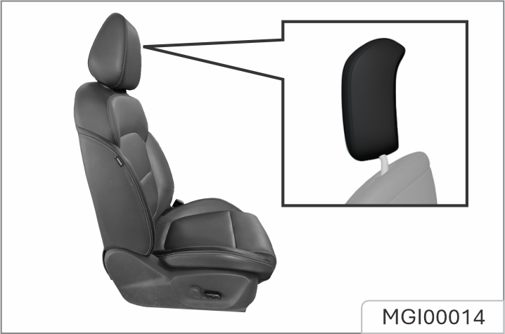
The front and rear seats of the vehicle have headrests that can be adjusted.
These headrests are not just for comfort; they are also meant to protect passengers from neck and spine injuries like whiplash during accidents, especially if the vehicle is hit from behind.
To stay safe in case of an accident, follow these steps when adjusting your headrests:
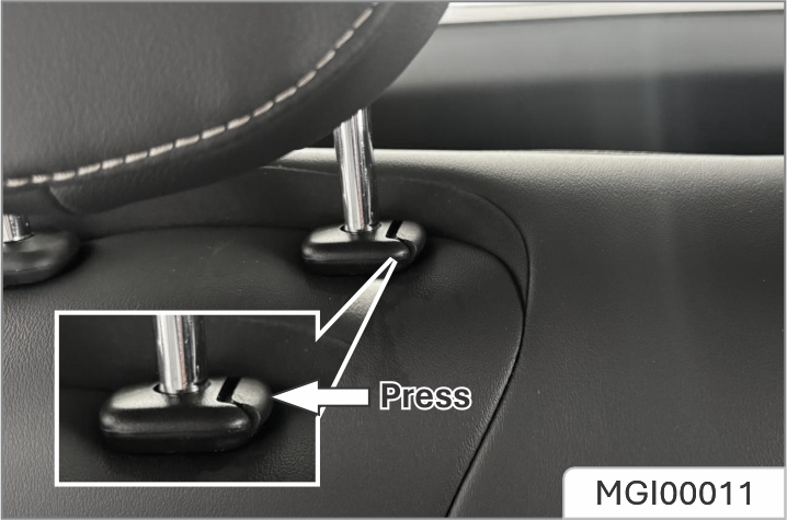
Head rest height adjustment To adjust the headrest upward, pull the headrest upward to a proper position and fix it. To remove the headrest, press and hold the release switch. To adjust the headrest downward, press and hold the release switch and push the headrest downward to a proper position, release the release switch for fixation. Do not press the headrest forcibly to avoid injuring the finger on the release switch.

In case of accidents, seat belts can provide good protection and that they must be used during driving is stipulated by regulations.
The seat belt is primarily designed for adult body sizes and is suitable for passengers with a height greater than 150 centimeters or a weight exceeding 36 kilograms. For children under 12 years old, please choose an appropriate child restraint system based on the child's size.
Please check all parts of the seat belt system for any wear or damage or abnormal function regularly. Please replace the damaged parts and components. It is strongly recommended to have the seat belt or deployed seat belt tensioner replaced at the JSW MG authorised service center after an accident.
a. Load limiter*: It is equipped on the front seat belt. The force limiter can reduce the stress applied on the body through the seat belt damping release in case of a collision accident.

Improper operation (for example removal or installation of seat belt or seat belt anchor buckle) will trigger the seat belt tensioner, leading to injury risks.
All passengers shall always fasten their seat belts before driving, and must wear seat belts under any circumstances during driving. In the event of an accident, passengers who do not wear or do not wear seat belts correctly may suffer serious injuries or deaths.
b. Wearing:
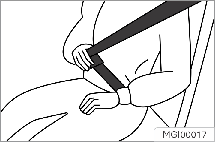
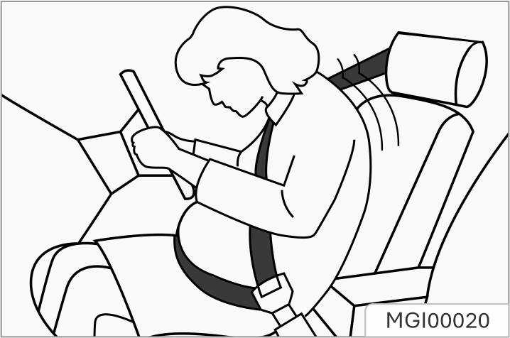
1. Pull out the seat belt from the retractor and guide it around the body without twisting. The shoulder belt shall span the whole shoulder obliquely, but shall not touch the neck or slip from the shoulder. The lap belt shall span the hip as low as possible.
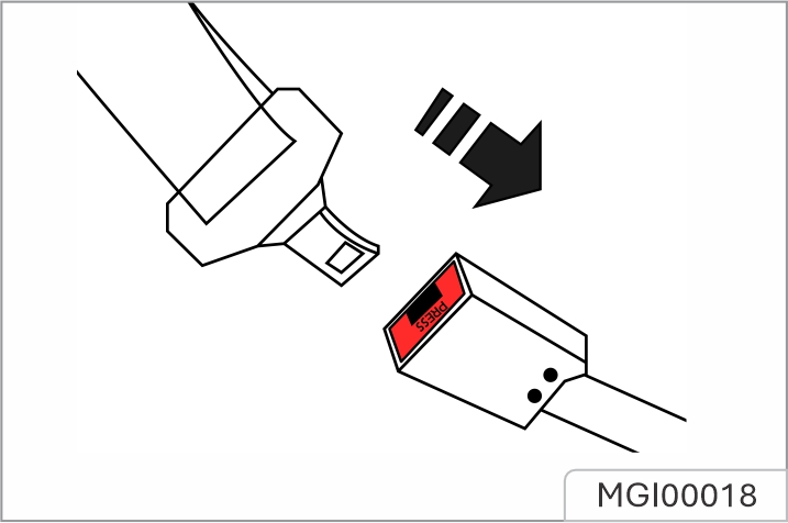
2. Inserting the latch plate forward (reverse insertion of the latch plate will cause the seat belt to twist, and cut or even endanger life in case of collision). Insert it into the buckle of the seat pair until a "click" locking sound is heard, and then pull it to check whether the locking is reliable. Pull the shoulder belt forcibly to adjust the tightness degree of crotch strap. The occupants can move in a small range when the vehicle stably runs, and the seat belt can be pulled out or retracted with the slow movement of the occupants.
Loose or heavy clothing will hamper close wearing the seat belt. Do not place any object (such as handbag and mobile phone) between the seat belt and your body.
c. Unlock:
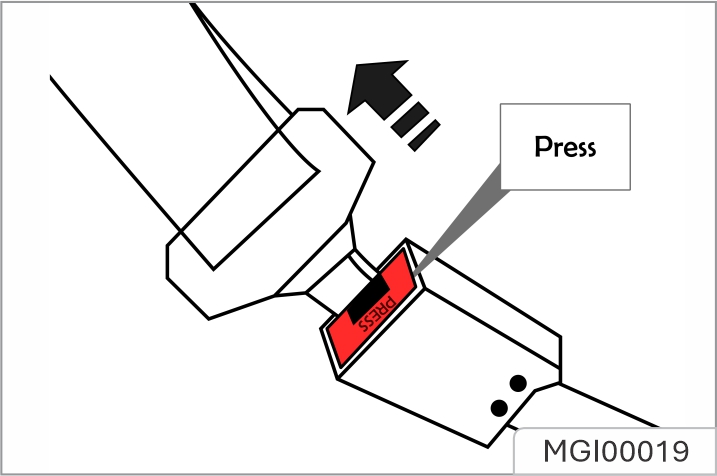
If you need to release the seat belt, press the red button on the buckle, and the tongue will automatically pop up and the seat belt automatically will retract. The seat belt is locked due to retracting or pulling out too fast, and it can be smoothly pulled out by loosening the webbing.
The crotch belt shall be placed as low as possible to go across the hip, so as to avoid force on the belly.
Use of seat belts during pregnancy
The seat belt provides protection for everybody, including a pregnant woman. Like all passengers, if pregnant women do not wear the seat belt, severe personal injuries are more likely to be caused to them.
The pregnant woman shall wear the hip/shoulder seat belt during the whole pregnancy, and the hip belt shall be fastened as low as possible.The best way to protect a fetus is to provide safety protection to its mother. If the seat belt is fastened correctly,the fetus is not vulnerable to injury in case of a collision. For a pregnant woman or any person, correct wearing is the key to exerting the best protection effect of the seat belt.
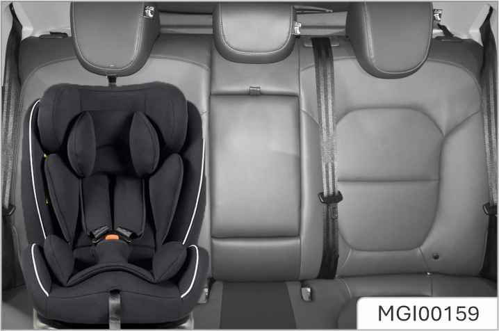
The vehicle is not equipped with a child seat. If you need one, a child seat that is applicable to ISOFIX "general" type can be selected. Child seat can only be placed on the 2nd row seat, because the front seat is not equipped with an anchor bracket. The statistical data of accidents show that placing the child seat on the second row seat can largely improve the child safety.
a. A young child shall always use the child seat. Never hold a baby in your arms while riding in the vehicle. Never allow a child to stand or kneel on a seat or in the luggage compartment when the vehicle is running.
b. An unfixed child seat may be thrown out of the vehicle in case of a collision or emergency stop, causing personal injuries to the driver and passengers. Be sure to properly secure the child seat even when it is not in use.
c. If the child seat is put in a closed compartment in hot weather, its temperature will be very high. Make sure that the child seat temperature is not very high before putting a child in the seat. If the child is too small and the seat belt cannot provide the best protection for him/her, please make sure that a proper child seat is used to provide safety protection.
d. The size and configuration range of the child seat is very wide. Not all child seats are applicable to your vehicle due to the interior trim as well as the seat shape and size. You have responsibility to ensure that the child seat installed matches with your vehicle and that the seat can be connected correctly to the vehicle with its anchor system. If the child seat does not match with your vehicle size and the child body figure or the connection to your vehicle is incorrect, severe personal injuries will be caused to the child and other passengers in the vehicle in case of a collision.
a. Types of child restraint system:
According to GB27887-2011, the child restraint system can be classified into 5 groups below:
Group 0: for children weighing less than 10 kg.
Group 0+: for children weighing less than 13 kg.
Group I: for child weighting more than 9 kg and less than 18 kg.
Group II: for child weighting more than 15 kg and less than 25 kg.
Group III: for child weighting more than 22 kg and less than 36 kg. Please select a suitable child seat according to the child weight and body figure.
For infants under one year old, their bones are very fragile, and a backward-facing child seat shall be used.
b. Applicability:
Below are different riding positions to child restraint system
| Quality Group | Seat (or Other | Positions) |
|---|---|---|
| Front passenger | Left/Right rear seat | |
| Group 0: < 10kg | X | U |
| Group 0+: < 13kg | X | U |
| Group I: 9kg~18kg | X | U |
| Group II: 15kg~25kg | X | U |
| Group III: 22kg~36kg | X | U |
|
Note: Meanings of letters in the table are as follows: U - applicable to universal child restraint system certified under this mass group. UF - Applicable to the forward-facing universal child restraint system approved by this quality group. L - applicable to special child restraint systems included in the list. Such restraint systems maybe for special, restricted or semi-general vehicles. B - applicable to built-in child restraint system approved for this mass group. |
Information on suitability of different ISOFIX positions for ISOFIX child restraint system
| Quality Group | Size Class | Fixture | Seat (or Other Positions) | |
|---|---|---|---|---|
| Seat Front Passenger | Left / Right Rear Seat | |||
| Carry-cot | F | ISO/L1 | X | IUF |
| Carry-cot | G | ISO/L2 | X | IUF |
| Carry-cot | 1 | |||
| Group 0: <10 kg | E | ISO/R1 | X | IUF |
| Group 0: <10 kg | (1) | |||
| Group 0+: <13 kg | E | ISO/R1 | X | IUF |
| Group 0+: <13 kg | D | ISO/R2 | X | IUF |
| Group 0+: <13 kg | C | ISO/R3 | X | IUF |
| Group 0+: <13 kg | 1 | |||
| Group I: 9kg~18kg | D | ISO/R2 | X | IUF |
| Group I: 9kg~18kg | C | ISO/R3 | X | IUF |
| Group I: 9kg~18kg | B | ISO/F2 | X | IUF |
| Group I: 9kg~18kg | B1 | ISO/F2 | X | IUF |
| Group I: 9kg~18kg | A | ISO/F3 | X | IUF |
| Group I: 9kg~18kg | (1) | |||
| Group II: 15kg~25kg | (1) | |||
| Group III: 22kg~36kg | (1) | |||
|
Note: For child restraint systems not marked according to ISO/×× size class (A~G), vehicle manufacturers shall specify the vehicle-specific ISOFIX child restraint system recommended for each seat. Note 2: Meanings of letters in the table are as follows: IUF - The seat is suitable for universal ISOFIX forward-facing child restraint systems approved for use in this mass group. IL - Applicable to special ISOFIX child restraint systems on the list. Such restraint systems maybe for special, restricted or semi-general vehicles. X - The ISOFIX position is not applicable to ISOFIX child restraint systems under this mass group and/or size class. |
c. Child seat fixing device:
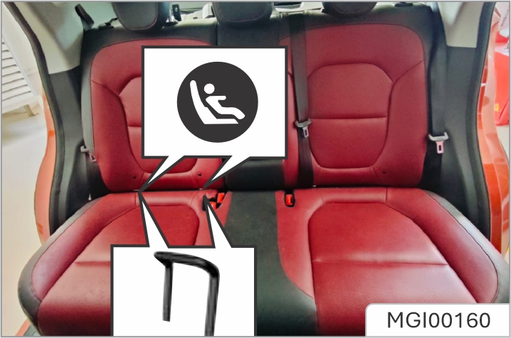
There is a set of fixing device on each of the right and left sides of the second row seat.
To fix the child seat:
1. The lower anchorage of child seat fixing device is on the joint between the rear row left and right seat backrest and the seat cushion back. Its position can be identified through the label on the lower edge of the backrest.
2. Clear up the objects on the seat. Note to remove the seat belt and seat belt buckle to avoid affecting accurate fixing of the child seat.
3. Put the child seat on the second row seat.
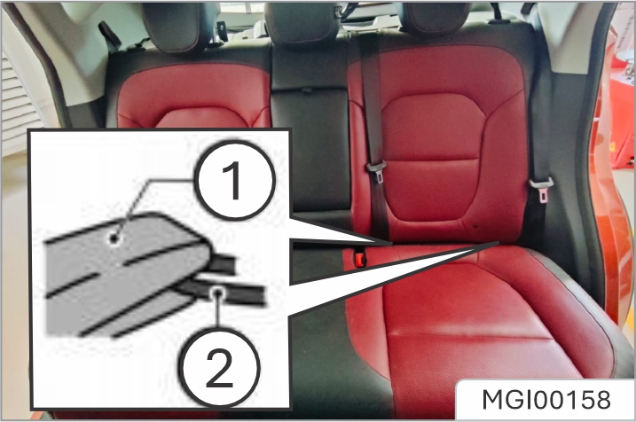
4. Child seat clamp, ② lower fixing point; connect the fixed hook on the child seat with the vehicle's fixed device.
Operate according to the child seat instructions.
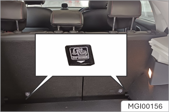
5. Connect the upper strap of the child seat to the corresponding fixing point of the vehicle. Refer to the child seat instructions to get to know when and how to strain the upper strap. As shown, the upper anchorage of child seat fixing device is located behind the rear seat backrest.
6. Push and pull the child seat in all directions to make sure it is safely secured.
7. Make sure that the child seat temperature is not very high before putting a child in the seat.
In case of a serious collision accident, the child seat fixing device may be damaged. Some parts may require repair and replacement. Please check the child seat fixing device after a collision.
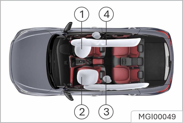
Please note that this is model and trim level dependant.
In the corresponding position where airbags are fitted, there is a warning sign stating 'AIRBAG'.
The airbag SRS provides ADDITIONAL protection in a severe frontal impact only. It does not replace the need, or requirement to wear a seat belt.
The airbags together with the seat belts provide optimum protection for adults, but it is not the case for infants. The seat belt and airbag systems in the vehicle are not designed for protecting infants.
The airbags together with the seat belts provide optimum protection for adults, but it is not the case for infants. The seat belt and airbag systems in the vehicle are not designed for protecting infants.
Airbag warning
 The airbag warning light is
located in the instrument
pack. If this lamp does not
extinguish or illuminates during
driving, it indicates that there is a
failure in the SRS or seat belt. Please
seek the JSW MG Authorised Service
Center at the earliest opportunity.
An SRS or seat belt fault may mean
the components may not be
deployed in the event of an accident.
The airbag warning light is
located in the instrument
pack. If this lamp does not
extinguish or illuminates during
driving, it indicates that there is a
failure in the SRS or seat belt. Please
seek the JSW MG Authorised Service
Center at the earliest opportunity.
An SRS or seat belt fault may mean
the components may not be
deployed in the event of an accident.
Front seat passengers should not place feet, knees or any other part of the body in contact with, or in close proximity to a front airbag. To minimise the risk of accidental injury from inflating airbags, seat belts should be worn correctly at all times. In addition, both driver and front seat passenger should adjust their seat to provide suicient distance from the front airbags.
If side airbags/curtain airbags are fitted, both driver and front seat passenger should be seated to maintain suicient distance from the upper part of the body to the sides of the vehicle, this will ensure maximum protection when the side airbags/curtain airbags are deployed.
When airbags are deployed, children without proper protection may suer from serious injury or even death. DO NOT carry children in the arms or on the knees during traveling.
Children should wear seat belts suitable to age. DO NOT lean out of windows.
An inflating airbag can cause facial abrasions and other injuries if the occupant is too close to the airbag at the time of its deployment.
DO NOT aix or place any objects on, or adjacent to the airbags. This may aect the airbag passage or create projectiles that may cause injury or serious harm in the event of airbag deployment.
After deployment the airbag components become very hot. DO NOT touch any airbag related components, it may cause burns or serious injury
DO NOT knock or strike the position where airbags or related parts are located, so as to avoid accidental airbag deployment which may cause serious injury or even death.
In the event of a collision, the airbag control unit monitors the rate of deceleration or acceleration induced by the collision, to determine whether the airbags should be deployed. Airbag deployment is virtually instantaneous and occurs with considerable force, accompanied by a loud noise.
Provided the front seat occupants are correctly seated and with seat belts properly worn, the airbags will provide additional protection to the chest and facial areas in the event of the car receiving a severe frontal impact.
Side airbags and curtain airbags are designed to oer additional protection to the side of the body facing the impact, if a severe side collision occurs.
Front Airbags
NEVER use a rearward facing child restraint on a seat protected by an ACTIVE AIRBAG in front of it, DEATH or SERIOUS INJURY to the CHILD can occur. Refer to 'Disabling the Passenger Airbag'.
Front seat passengers should not place feet, knees or any other part of the body in contact with, or in close proximity to a front airbag.
In extreme cases driving on very uneven surfaces may cause airbag deployment. Please take extra care when driving on uneven roads.
Airbags are designed to deploy during serious impacts, the following conditions may cause airbag deployment.
Seat Side Airbags *
The manufacture and material of the seat is critical to the correct operation of side airbags.
Therefore, please DO NOT fit seat covers which may aect side airbag deployment.
In the event of a serious side impact, the relevant side airbag will deploy (only the aected side).
Curtain Airbags *
In the event of a serious side impact, the relevant side curtain airbag will deploy (only the aected side).
Condition in which airbags will not deploy
The deployment of airbags does not depend on the vehicle speed, but on the object that the vehicle hits, angle of impact and the rate at which the car changes speed as a result of a collision. When the impact force of collision is absorbed or dispersed to vehicle body, airbags may not deploy; however, airbags may sometimes deploy according to impact condition. Therefore, the deployment of airbags shall not be judged based on the severity of vehicle damage.
Front Airbags
Under certain conditions the front airbags may not be deployed. Some examples are listed below:
Seat Side Airbags and Curtain Airbags *
Under certain conditions the seat side and side head airbags may not be deployed. Some examples are listed below:
Disabling the Passenger Airbag
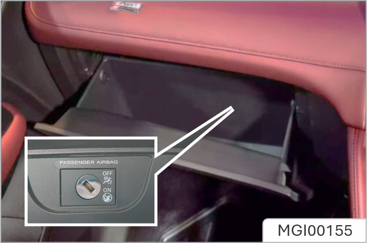
The passenger airbag disable switch is located inside of the glove box, To disable the passenger airbag, insert the key and turn the switch to OFF position.
The passenger airbag disable switch is located inside of the glove box, To disable the passenger airbag, insert the key and turn the switch to OFF position.
When the switch is turned to the OFF position, the OFF indicator light (located in the PAB display panel in the lamp assembly) illuminates, this indicates that the passenger airbag is disabled.
When the switch is turned to the ON position, the ON indicator light (located in the PAB display panel in the lamp assembly) illuminates, this indicates that the passenger airbag is enabled.
Service and Replacement of Airbags
Service Information
DO NOT install or modify the airbag. Any changes to the vehicle structure or airbag system wiring harness are strictly prohibited.
Changes to vehicle structure is prohibited. This may aect the normal operation of the SRS.
DO NOT allow these areas to be flooded with liquid and DO NOT use petrol, detergent, furniture cream or polishes.
If water contaminates or enters the SRS it may cause damage and aect deployment. In this case contact the JSW MG Authorised Service Center immediately.
To prevent damage to the airbag SRS, the following areas should be cleaned sparingly with a damp cloth and upholstery cleaner ONLY:
If the airbag warning lamp fails to illuminate, stays on, or if there is damage to the front or side of the vehicle, or the airbag covers show signs of damage, contact the JSW MG Authorised Service Center immediately.
Replacing Airbag System Parts
Even if the airbag does not deploy, collisions may cause damage to SRS in the vehicle. Airbags may not function properly after damage, and can not protect you and other passengers when a second collision occurs, which may cause serious injury or even death. To ensure that SRS can function properly after collision, please go to the JSW MG Authorised Service Center to check airbags and repair as necessary.
Airbags are designed for using once only.
Once the airbag is deployed, you must replace SRS parts.
Please go to the JSW MG Authorised Service Center for replacement.
Disposal of Airbags
When your vehicle is sold, ensure that the new owner knows the vehicle is equipped with airbags, and is aware of the replacement date of SRS.
If the vehicle is scrapped, the undeployed airbags may have potential risks, therefore, before the disposal, they must be deployed safely in a certain environment by a professional from the JSW MG Authorised Service Center.
When shall the airbag be inflated? The frontal airbag is designed to be inflated in moderate to severe head- on collision or almost head-on collision to reduce severe injury risks ofthe driver's and the front passenger's head and chest.
Frontal airbag inflation is not primarily dependent on the speed of the vehicle, but on the object being collided with, the direction of the collision and the deceleration of the vehicle per unit time during the collision. The frontal airbag may be inflated at different collision speed. It depends on whether the vehicle hits the object straight or at an angle at the moment of the collision, and on whether the collided object is fixed or moving, non- deformable or deformable, narrow or wide. Due to different designs of each model, the collision inflation conditions of the frontal airbag may vary. Frontal airbags do not inflate in the event of a vehicle rollover, a rear collision and many side collisions. The frontal airbag may not inflate in slight head- on or nearly head-on collisions, lateral or diagonal collisions, collisions to cylindrical objects (such as telegraph pole and tree trunk), rear-end collisions under
large vehicle (trucks, etc.) breast board and lateral glancing collisions. As per the design, the seat lateral- impact airbag and the side curtain airbag will inflate according to the impact position in case of the moderate to severe lateral collisions.
The seat lateral-impact airbag and the side curtain airbag may not inflate in slight side collisions and lateral-frontal or diagonal collisions. As per the design, the seat lateral- impact airbag and the side curtain airbag will inflate on the collision side of the vehicle. Airbags are not triggered in every collision. For a particular accident, it shall not simply judge whether the airbag should be inflated according to the causalities, vehicle damage or repair and maintenance expenses. Your vehicle is equipped with a collision sensing and diagnosis module. If a collision accident reaches certain strength, the module may record relevant collision information after the collision. If you have any questions about the airbag working condition of your vehicle in a collision accident, please contact the JSW MG authorised service center in time for professional analysis and diagnosis.
How is the airbag inflated? During inflation, the sensing system sends an electronic signal that triggers the gas generator to release gas to fill the airbag, causing the airbag to inflate and eject from the cover. The gas generator, airbag and relevant members are all components of the airbag module. Please refer to "Airbag Position" for details.
How does the airbag provide protection? The airbags supplement the protection provided by the seat belts by distributing the impact forces more evenly over the occupant's body. However, in collisions where the occupant's body is not moving in the direction of the airbag, and in collisions where an external object has entered the vehicle, the airbag is unable to provide the appropriate protection. The airbag shall only be seen as a supplementary device to the seat belt.
When the airbag is inflated, dust may be spread in the air. All persons in the vehicle shall get off the vehicle as soon as possible. If you have a breathing problem and cannot get off the vehicle after airbag inflation, open the windows or doors to get fresh air. If breathing problems occur after the airbag is inflated, you should seek medical attention as soon as possible.
What will you see after the airbag inflates? When the airbag is inflated, it will deflate so quickly that some people may not even notice that the airbag has been inflated because it deflates so fast. Smoke and dust may also be emitted from the deflated airbag vent. If the vehicle power supply system can still work normally after a collision, the vehicle has the functions of automatically unlocking doors, turning on hazard warning lamps and turning off fuel system after airbag inflation. The driver can use corresponding function switch to lock doors, turn off indoors lamps and turn off the hazard warning lamp. The deployment of the front passenger air bag may also cause damage
if the airbag cover is damaged, opened or broken, the airbag may not function normally. It shall be repaired as soon as possible.
Never stick or cover any object on the airbag cover surface or refit the airbag cover; never try to repair, adjust or remove or install any airbag system component; never try to refit the front bumper of the vehicle body by yourself.
Other situations where the airbag may be inflated (deployed) except for a collision The airbags may also inflate if the underside of the vehicle suffers a severe impact.
Foot Brake
The free stroke of brake pedal is in the range of 0~30mm.
For added safety, the hydraulic braking system operates through dual circuits. If one circuit should fail, the other will continue to function, but greater pedal pressure will be needed, and increased brake pedal travel, and longer stopping distances will be experienced.
In the event of a brake failure where only one circuit is operational, the car should be brought to a halt as soon as traic conditions safely allow. DO NOT continue driving – seek the JSW MG Authorised Service Center.
Servo Assistance
The braking system is servo assisted, always be aware of the followings during the operation:
Wet Conditions
Driving through water or heavy rain may adversely aect braking eiciency. In this case, keep a safe distance from other vehicles and intermittently apply the brake pedal to keep the brake disc surface dry.
![]() Your car is equipped with
EBD, which, in order to
maintain braking
eiciency, distributes braking forces
between front and rear wheels,
under all load conditions. EBD
integrates a monitoring system. The
monitoring system is linked to the
brake system malfunction indicator
lamp on the instrument pack. If the
indicator lamp illuminates while
driving, or remains illuminated after
the START/ STOP Switch is turned on
(ON/RUNNING position) and the
parking brake is released, it
indicates there is a failure with the
braking system, and the EBD may be
inoperative.
Your car is equipped with
EBD, which, in order to
maintain braking
eiciency, distributes braking forces
between front and rear wheels,
under all load conditions. EBD
integrates a monitoring system. The
monitoring system is linked to the
brake system malfunction indicator
lamp on the instrument pack. If the
indicator lamp illuminates while
driving, or remains illuminated after
the START/ STOP Switch is turned on
(ON/RUNNING position) and the
parking brake is released, it
indicates there is a failure with the
braking system, and the EBD may be
inoperative.
In such a case, stop the car immediately and contact the JSW MG Authorised Service Center as soon as possible. DO NOT drive the car with the brake system malfunction warning light illuminated.
Electronic Brake Assistance (EBA)*
Your car is equipped with EBA, which reacts to the speed at which the brake pedal is applied. If, in an emergency situation the brakes are applied faster than the limits set within the system, then full ABS application is applied to bring the car to a stop in the shortest possible distance.
Stability Control System (SCS)
SCS is designed to assist the driver in control of driving direction. The SCS is automatically activated after the engine is started. When SCS detects that the vehicle is not moving in the intended direction, it will intervene by applying brake force to selected wheels or through the engine management system to prevent sliding and assist in bringing the car back to the right direction.
Traction Control System (TCS) *
![]() The purpose of TCS
is to aid traction and
driving stability,
thereby helping the
driver to maintain
control of the car. The TCS monitors
the driving speed of each wheel
individually. If spin is detected on
one wheel, the system
automatically brakes that wheel,
transferring torque to the opposite,
non spinning wheel. If both wheels
are spinning, - the system will
reduce the output torque of the
power system in order to regulate
wheel rotation until traction is
regained.
The purpose of TCS
is to aid traction and
driving stability,
thereby helping the
driver to maintain
control of the car. The TCS monitors
the driving speed of each wheel
individually. If spin is detected on
one wheel, the system
automatically brakes that wheel,
transferring torque to the opposite,
non spinning wheel. If both wheels
are spinning, - the system will
reduce the output torque of the
power system in order to regulate
wheel rotation until traction is
regained.
Switching On/Off
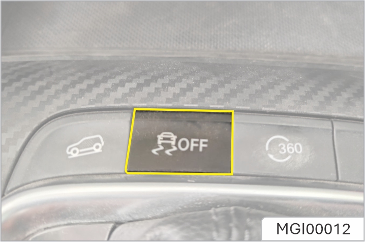
With the START/STOP Switch is switched ON/RUNNING, SCS and TCS will automatically turn on. And you can turn them o after the engine is started. Press SCS switch (less than 2 seconds) to turn o TCS.
Press the SCS switch (more than 10 seconds), it will be regarded as misoperation.
Disabling SCS and TCS will not aect the operation of ABS. Always TCS when driving with snow chains fitted.
Stability control /Traction control warning lamp
Refer to "Warning light & indicators" in "Instruments & Controls" section.
Hill Hold Control (HHC) *
HHC has limitations when subject to adverse conditions such as wet or icy surfaces and steep slopes. The driver must always maintain control of the vehicle and attention should not be reduced just because HHC is enabled.
HHC is not a substitute for parking brake application when carrying out a hill start. This system is only suitable for use as a start assist during driving. DO NOT exit the vehicle with only HHC applied, otherwise it may lead to a serious accident when HHC releases.
In order to prevent the vehicle from accidentally rolling backward during hill start under a stop and go road condition, please step on the brake pedal deeply for several seconds before start.
The HHC helps the driver to start when going uphill, and prevents the vehicle from rolling backward. The following conditions must be fulfilled to activate the HHC:
The HHC is available in both forward and backward directions when pulling away on uphill slopes.
Hill Descent Control (HDC) *
The HDC system is only an auxiliary function. It has limitations when subject to adverse conditions such as wet or icy surfaces and steep slopes. The HDC system cannot overcome the laws of physics, always ensure that the vehicle is driven down steep slopes at low speeds.
Even when the HDC system is switched on, the driver must always pay close attention to the driving state of the vehicle, and take active control when necessary. In certain cases, HDC may be suspended or switched o temporarily.
During some driving conditions on downhill surfaces (e.g. driving down a slope at high speed or small slope, etc.), HDC is inoperative, the driver must maintain control of the vehicle at all times and use brake applications to ensure safety.
The HDC system is an auxiliary function specially designed for driving on acute down hill gradients. The system reduces the speed by applying brake force, thus assisting the driver to drive on acute downhill surfaces with low speeds. Please DO NOT use this function when driving on the ordinary roads. When the HDC is working, the brake system may generate strong vibrations or noise. It is normal during the operation of HDC.
During the operation of the hill descent control (HDC) system, please do not move the shift control knob to the “N” position. Such operation may deactivate the HDC function.
HDC System On/Off
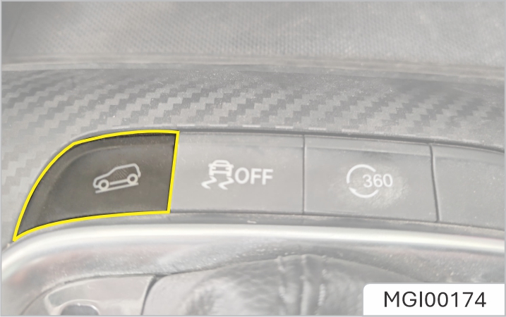
When the START/STOP Switch is switched ON/RUNNING, HDC system defaults to o. Use the switch to turn the HDC system on/ o. Normally, HDC system has four states:
![]()
When the vehicle turns at a fast speed whilst on an incline, the HDC system may switch from Standby to Operating mode.
During HDC system operation the braking system will automatically pressurise and maintain pressure. Operation of the brake pedal during this phase may result in a 'kickback' sensation through the pedal. This is normal for HDC operation.
HDC ON malfunction indicator lamp
Refer to "Warning light & indicators" in "Instruments & Controls" section.
Anti-lock Brake System (ABS)
ABS cannot overcome the physical limitations of stopping the car in too short a distance, cornering at too high a speed, or the danger of aquaplaning, i.e. where a layer of water prevents adequate contact between the tyres and the road surface
The purpose of the anti-lock braking system (ABS) is to prevent the wheels from locking while braking, thereby enabling the driver to retain steering control of the car.
The fact that a car is fitted with ABS must never tempt the driver into taking risks that could aect his/her safety or that of other road users. In all cases, it remains the driver's responsibility to drive within normal safety margins, having due consideration for prevailing weather and traic conditions.
Under normal braking conditions, ABS will not be activated. However, once the braking force exceeds the available adhesion between the tires and the road surface, thereby causing the wheels to lock, ABS will automatically come into operation. This will be recognisable by a rapid pulsation felt through the brake pedal.
Braking in an Emergency
DO NOT pump the brake pedal at any time; this will interrupt the operation of ABS and may increase the braking distance.
If an emergency situation occurs, the driver should apply full braking eort even when the road surface is slippery. ABS will ensure that the wheels do not lock and that the car is brought to a halt in the shortest possible distance for the prevailing road surface conditions.
On soft surfaces such as powdery snow, sand or gravel, the braking distance produced by the ABS system may be greater than that for a non-ABS system, even improved steering would be experienced. This is because the natural action of locked wheels on soft surfaces is to build up a wedge of material in front of (or to the side of, if steering) the tyre contact patch. This eect assists the car to stop when braking or to change direction when steering.
No matter how hard you brake, you are still able to continue steering the vehicle as normal.
ABS can not reliably make up for the driver's mis-operation or lack of experience.
ABS Malfunction Indicator Lamp
Refer to "Warning light & indicators" in "Instruments & Controls" section.
The normal (non-ABS) braking system remains fully operational and is not aected by partial or full loss of ABS. However, the braking distances may increase.
Active Rollover Protection (ARP) *
The ARP system cannot overcome the laws of physics. It is a driver aid to assist the stability of the vehicle and under extreme conditions. It is not a guarantee that the car will not roll over.
In case that the vehicle with high centre of mass due to dynamic driving (such as change lane) or stable driving (such as loop driving) may roll over, ARP brakes the outside wheels to under-steer, thereby preventing the vehicle from rollover.
During ARP application the steering characteristics of the vehicle may be noticeably dierent from normal.
Emergency Braking Hazard Warning Lights Control System (HAZ)
If the vehicle is traveling at high speed and the driver makes an emergency braking manoeuvre, the system will automatically flash the brake lamps to warn the following drivers, thereby eectively reducing the risk of rear-end collision accidents
If the hazard warning lights are being operated manually, the HAZ function will be disabled.
After the HAZ function is activated, when the emergency braking manoeuvre is exited (no severe deceleration detected) then the function will be switched o after a few seconds.
If the vehicle speed is less than 10 km/h when the brake lamp flashes out, the hazard warning lights will illuminate automatically. The hazard warning lights can be turned o by short pressing the hazard warning light switch or speeding up the vehicle to above 20 km/h for more than 5 seconds
Never drive the vehicle without releasing the parking brake or pull up the parking brake while the vehicle is moving. Doing this may cause the vehicle to lose control, the ABS will not work and may damage the rear wheel brakes.
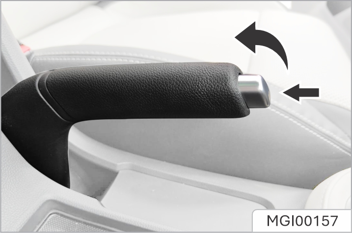
The parking brake only acts on rear wheels. Pull up the parking brake lever, and the parking brake will act. When you stop the vehicle, make sure that the parking brake lever is always pulled up. To release the parking brake, pull up the parking brake lever slightly, and then press the button at the front end of the lever (as shown by the arrow in the figure) to fully lower the parking brake lever. When parking on steep slopes, don't just rely on the parking brake to brake.
In the event of EPB malfunction where EPB release is not possible, please consult the JSW MG Authorised Service Center in order to carry out an emergency manual release of the parking brake.
Applying the EPB
While the vehicle is stationary, the EPB can be applied. Ensure the EPB is applied every time the vehicle is left or parked.
An audible motor noise may be heard when applying or releasing the EPB.
In the event of a flat battery or power failure, it is not possible to apply or release the EPB. In such a case, 'jump leads' shall be used for emergency engine start, please refer to “Emergency Starting” in “Emergency Information” chapter
Releasing the EPB
Starting Aid
The EPB can predict the driver's intention and automatically release the EPB. If the driver's seat belt is fastened, the engine is started up, D or R gear is selected and the accelerator pedal is depressed for start o, the EPB will automatically release.
When auto hold stops the vehicle for reasons such as flameout, releasing the seat belt or pressing the auto hold switch, the electronic parking brake is applied. It cannot be guaranteed that the vehicle will be stabilised in all cases. For example,
the rear wheels are on a slippery road surface, or the vehicle incline is too great (larger than 20%). Please make sure that the vehicle is safely stabilised prior to exiting.
DO NOT take any extra risks when driving due to the fact the vehicle is fitted with additional convenience functions. The driver should pay full attention and observe the surroundings even if the vehicle is equipped with Auto Hold system. The auto hold function cannot guarantee the stability of the vehicle when starting o or braking on hills especially on slippery or icy surfaces.
DO NOT leave the vehicle when the engine is running and the auto hold is active. Auto hold cannot guarantee the electronic parking brake operation in all cases after flameout. Please ensure the electronic parking brake is applied and the vehicle is stabilised prior to exiting the vehicle. The auto hold function should be switched o during the use of a car washer for automatic car washing, otherwise the electronic parking brake may suddenly apply and cause vehicle damage.
With the engine running, if the vehicle is required to stop for long periods or frequently for long periods (such as wait at the traic lights, stop on a slope or stop and go with traic), the auto hold function can assist the driver in stabilising the vehicle, enabling you to remove your foot from the brake pedal when the vehicle is stationary and the Auto Hold active. Auto hold has 3 main states:
1. Off:The function in Off state
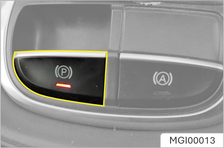
2. Standby:The function is in Standby state, when the function is activated but the vehicle is not parked, and the indicator light of auto hold switch is on. Once the vehicle has stopped, and all other conditions are met, the system will automatically select Park.
3. Parking:The function in Parked state. In this state the green lamp in the instrument pack illuminates. With the driver's seat belt fastened, the door closed and the engine running, press the auto hold switch to switch the auto hold function from O to Standby state. With the brake pedal firmly pressed and the vehicle completely stopped, the auto hold function will switch from the Standby state to the Parking state. When the auto hold is in the Parking state, engaging D or R and pressing the accelerator will automatically release the auto hold function.
In some circumstances such as releasing the seat belt, flameout or remaining static for a length of time, it will result in the vehicle exiting the auto hold Parking state and applying the electronic parking brake.
With the brake pedal pressed, operating the switch to turn the auto hold o, the system will NOT apply the parking brake. It is recommended to turn o the auto hold function when reversing into the parking space.
Emergency Braking Function
Inappropriate use of the EPB can lead to accidents and injuries. Do not apply the EPB for vehicle braking, unless in emergency. During emergency braking using the EPB, DO NOT switch o the ignition, this could result in serious injury.
When the car is in motion, in case of any emergency, such as the car cannot be stopped by the brake pedal, it can be decelerated by pulling up and holding EPB switch.
The EPS system provides steering assistance for the vehicle. This system does not need power steering fluid, which brings great convenience for the daily vehicle maintenance.
When the power supply is turned on, the EPS MIL illuminates momentarily. The EPS warning lamp does not go out or illuminates when the vehicle is running, indicating that there is a fault in the EPS system. In case of such condition, there is a need to go to JSW MG authorised Service Center for check in time. When the EPS system is under extreme conditions of high load work for a long time (For example, the steering wheel is “turned to the end” for a long time, or the vehicle is moved into the garage at a low speed repeatedly to a wide angle), the time you have to steer the wheel with great force. If you need to restore normal power assistance, you can steer the wheel at a smaller angle or increase the speed. You can restart the vehicle if necessary.
The EPS system will adjust the power assistance according to the vehicle speed. As a result, the steering wheel can beturned easily at low speed and be turned relatively steadily at high speed.
Illuminated EPS warning lamp can indicate that the electronic power steering column cannot work normally. If you fail to keep the steering column in an agreeable working condition, collision may happen and as a result, personal injuries, and damage to the vehicle or other properties can occur.
a. EPS fault warning lamp
![]() When the vehicle is powered on, the warning lamp will illuminate instantaneously. It indicates
that
the system is conducting self inspection and the warning lamp bulb can work normally. The
warning
lamp goes out several seconds later. When the electronic power steering (EPS) system detects a
fault, the warning lamp will give out an indication. When the steering system has a fault, the
vehicle can still steer, but requires much greater eort. In case of the following circumstances,
please consult the nearest JSW MG authorised service center.
When the vehicle is powered on, the warning lamp will illuminate instantaneously. It indicates
that
the system is conducting self inspection and the warning lamp bulb can work normally. The
warning
lamp goes out several seconds later. When the electronic power steering (EPS) system detects a
fault, the warning lamp will give out an indication. When the steering system has a fault, the
vehicle can still steer, but requires much greater eort. In case of the following circumstances,
please consult the nearest JSW MG authorised service center.
In case of indication continuously ON. Do not drive the vehicle in this condition. Get the vehicle checked. Contact JSW MG authorised service center.
Adjustment of Steering Wheel
DO NOT attempt to adjust the position of the steering wheel while the vehicle is in motion. This is extremely dangerous.
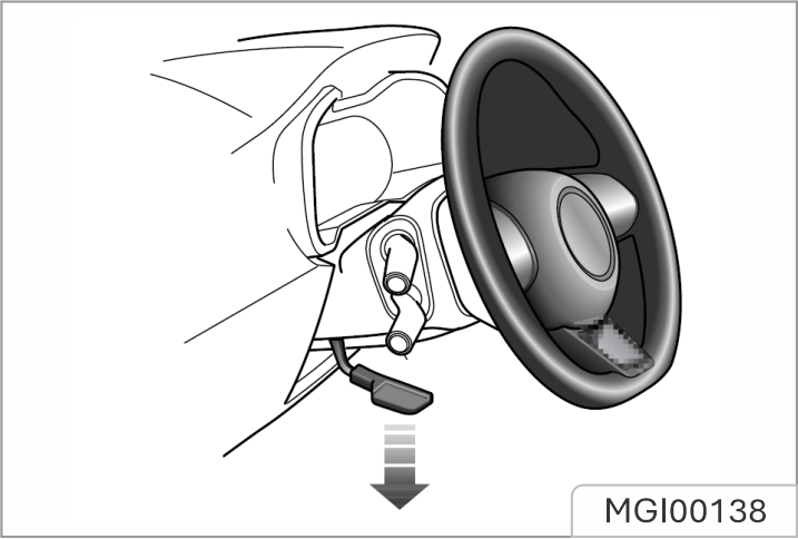
To adjust the angle of steering wheel to suit your driving position:
Steering Mode Switching
The electric power steering system provides 3 dierent steering modes:
Please start the vehicle when the vehicle is stationary and enter the entertainment to switch the steering mode.
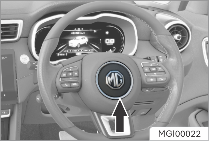
Press the horn button area on the steering wheel (as indicated by the arrow) to operate the horn.
The vehicle horn switch location and the driver’s airbag are located in close proximity on the steering wheel. The illustration shows the position of the horn switches, please ensure that you press in this area to avoid any potential conflict with the operation of the airbag.
To avoid possible SRS issues, please do, not press with excessive force or hit the airbag cover when operating the horn
When the vehicle is in motion, DO NOT switch o the ignition or remove the key, otherwise the steering wheel may be locked, making it impossible to turn the vehicle.
When the vehicle is in motion, DO NOT touch the key to avoid engine flameout!

The START/STOP Switch is located on the right side of the steering column. Function of each position is as follows:
Position LOCK/OFF
Position ACC
Position ON/RUNNING
Position START
The key can only be turned from ACC position to LOCK/OFF position when the shift lever is in P (parking) position
When the START/STOP Switch is in the OFF position, if the driver side door is opened, an audible warning sounds to indicate that the key has not been removed.
When the steering wheel is locked and the key cannot be turned from the OFF position to the ACC position, please turn the steering wheel slightly whilst turning the key to unlock the steering wheel.
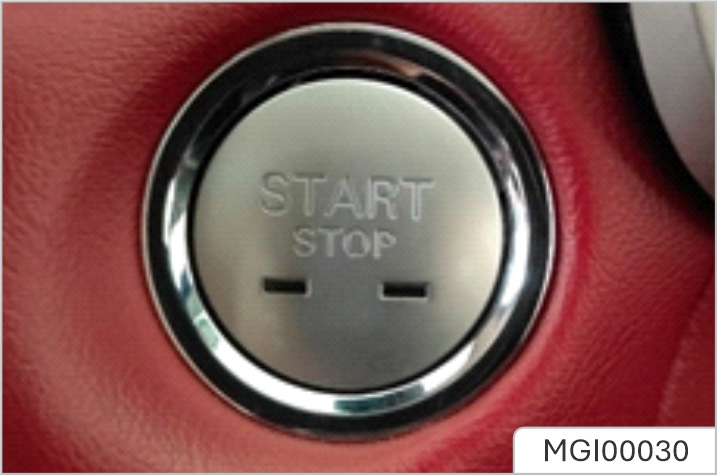
The keyless START/STOP Switch is located in the fascia to the left of the steering column, it is a push button style switch.
To operate the system, the remote key must be in the car. To remove the gear lever from the Park position, the START/STOP Switch must be in ON/RUNNING position, and the brake pedal must be depressed.
The operational status displays are as follows:
Indicator Off (OFF)
Yellow Light (ACC)
Green Light (ON/RUNNING)
After turning the START/STOP Switch to the OFF position and opening the door, if the key is still left in the vehicle, the audible warning will sound when closing the door, to remind you that the key is still in the vehicle.
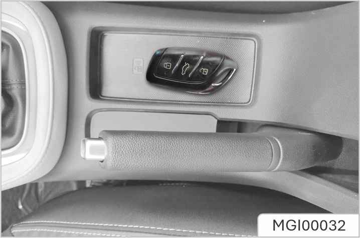
If your car is subject to strong radio signals the keyless entry and start systems may suer from interference and not function correctly. Please see the 'Alternative Starting Procedure'.
Never start or leave the engine running in an unventilated building. Exhaust gases are poisonous and contain carbon monoxide, which can cause unconsciousness and may even be fatal.
Catalytic converters and particulate filters can be damaged if the wrong fuel is used, or if an engine misfire occurs. Before starting the engine, please read carefully the contents in the “Catalytic converter and Particulate Filter” section.
Operation of Starting the Engine
When the shift lever is in any other position, the engine cannot be started.
After the engine starts, if the key is not released immediately, the starter will continue to work, which will not only discharge the battery, but also damage the starter and starter motor, catalytic converter and particulate filter.
Starting the Engine:
Alternative Starting Procedure (Auto Transmission)
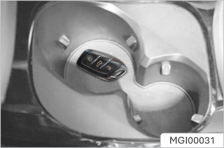
If the car is located in an area where there are strong radio signals causing interference or the smart key battery condition is low, please use the following steps to attempt to start the car:
If the immobiliser cannot be released after the car has left the area of strong radio interference or had the smart key battery replaced please consult the JSW MG Authorised Service Center.
Alternative Starting Procedure (Manual Transmission)
If the car is located in an area where there are strong radio signals causing interference or the smart key battery condition is low, please use the following steps to attempt to start the car:
If the immobiliser cannot be released after the car has left the area of strong radio interference or had the smart key battery replaced please consult the JSW MG Authorised Service Center.
EngineIdle speed will decrease after engine warm-up. Do not increase engine speed immediately after engine starts. Progressively operate the engine and transmission so that oil can preheat and lubricate all operating components
DO NOT press the accelerator pedal while starting and DO NOT operate the starter for more than 15 seconds at a time.
In temperatures of -10°C and below, engine cranking times will increase. It is essential that all unnecessary electrical equipment is switched o while cranking.
Stop the engine as follows:
After strenuous towing or driving at high speed (particularly in hot weather), it is suggested to allow the engine to idle for a few minutes before switching o, which enables the cooling system to work continuously to lower the engine temperature.
The engine, transmission, brakes and tyres need time to 'bed-in' and adjust to the demands of everyday motoring. During the first 1500 km, please heed the following advice so as to enhance the long-term operation performance:
After 1500 km, engine speeds can be gradually increased.
Your vehicle has been designed with the latest technology in order to minimize the environmental impact of exhaust emissions.
The way in which you drive your car has a significant bearing on the life span of the car and battery.
Drive Smoothly
Anticipating obstructions and slowing down well in advance, avoids the need for unnecessary acceleration and harsh braking.
A smooth driving style not only improves battery/distance performance, but can reduce the amount of wear on the brakes and tyres.
Avoid Driving at Maximum Speed
Fuel consumption and noise levels rise significantly at higher speeds.
Driving Foreseeingly
Avoid roads with traic congestion or traic jams. Foresee road congestion as early as possible and keep enough distance to the front car during driving, and slow down in time. Avoid stamping on the brake pedal for long time if there is no braking need, which will cause friction plate overheating and premature wear.
Use of Electrical Equipment
Use of electrical equipment will reduce the power available from the battery. Whilst it is essential to maintain a comfortable interior environment, excessive use of system such as A/C will increase power consumption and reduce the vehicle range.
Driving in Rain or Snow
Emergency braking, accelerating and steering on slippery roads will reduce the vehicle's handling performance and grip.
Driving through Water
Avoid driving through floods after heavy rain, which may lead to serious damage to the vehicle.
Have the Vehicle Regularly Serviced
Regularly servicing will ensure optimum fuel consumption and minimize exhaust pollutants, as well as effectively extending the services life of the car.
Check Tyre Pressures Regularly
Under-inflated tyres increase the rolling resistence of the car which, it turn, increase fuel consumption . Over or under-inflated tyres wear out more rapidly and also have a detrimental effect on the car's handling characteristics.
Do not carry unnecessary loads
The additional weight of unnecessary loads waste fuel, especially in stop/start condition where the car is frequently required to set off from stationary.
Maintain Correct Four-wheel Alignment
Maintain the correct wheel alignment. Avoid collisions with the kerb and reduce speed on uneven road surfaces. Out of specification wheel alignment will not only lead to excessive tyre waer, but also increase the load and fuel consumption.
DO NOT let the vehicle pass through or park on the road or ground with combustible materials such as hays or leaves etc. which can come into contact with the exhaust system to avoid fires.
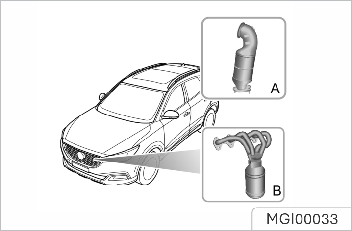
The exhaust system incorporates a catalytic converter, which converts poisonous exhaust emissions from the engine into environmentally less harmful gases.
Depending on dierent models, the vehicles are equipped with dierent three-way catalytic converters: three-way catalytic converter for 1.3T models (A) and three-way catalytic converter for 1.5L models (B).
Improper use may lead to damage to the catalytic converter, so please pay special attention to the following requirements to minimize the possibility of damage.
Fuel
Starting
Driving
the vehicle is driving with a gear engaged. If the vehicle equipped with a manual transmission needs to slow down while traveling in high gear, downshift immediately to avoid insuicient driving force.
Unauthorized engine modification is prohibited. because engine modification may result in engine misfire, loss of engine power or engine shaking, etc. ewhich could seriously damage the catalyst converter.
Regularly maintenance must be carried out in accordance with the schedule specified in the 'Service Portfolio'
Use only the recommended fuel which meets national standard! Serious damage to the catalytic converter, a reduction in engine power/torque and increase in fuel consumption will occur if the wrong fuel is used.
Please use the fuel which is recommended and certified by the manufacturer. See 'Major Parameters of Engine' in 'Technical Data'. If a lower grade of fuel is used, an engine knocking noise may occur, please use the recommended or above grade fuel as soon as possible. If the engine knocking noise is still noticeable after using the recommended or above grade fuel, please contact the JSW MG Authorised Service Center immediately.
Safety Precautions in a Fuel Filling Station
Vehicle fuel gases are highly flammable and, in confined spaces, are also extremely explosive.
Always take care when refueling:
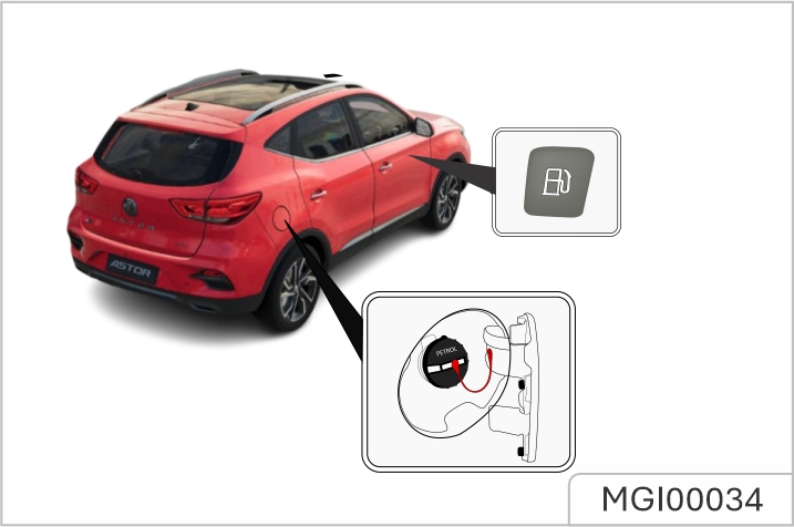
Fuel Filler Flap
The fuel filler flap is located on the rear right-hand wing. Pull the fuel filler flap release handle under the driver side instrument pack to open the flap.
Fuel Filler Cap
Unscrew the filler cap anticlockwise and allow any pressure inside the tank to escape, before removing the cap. After refueling, tighten the filler cap clockwise until you hear 1 “click” sound.
Do not fully fill the tank if the vehicle is to be parked in direct sunlight, or high ambient temperature - expansion of the fuel could cause spillage. The fuel filler tube is designed to accept a narrow, long filler nozzle. There is a cover at the filler neck, by inserting the filler nozzle thoroughly before fuel filling, the cover can be fully opened. Start the engine after fuel filling. After refueling, if the engine runs unevenly, switch o and seek the JSW MG Authorised Service Center before attempting to restart the engine.
The following information is very important, please read carefully before use.
The automatic transmission is a 6 speed transmission.
The highlighted letters or numbers in the information centre indicate the selected gear or mode.
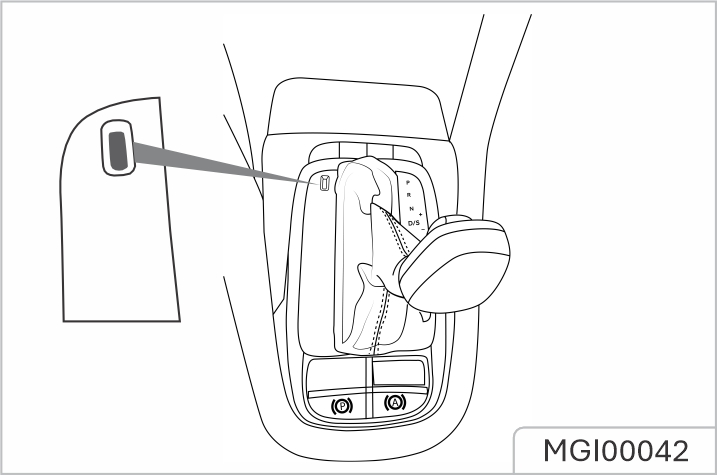
A sprung loaded lock button, located in the gear lever, is used to prevent mistakenly selecting P (Park) or R (Reverse) whilst the gear selector is in other positions.
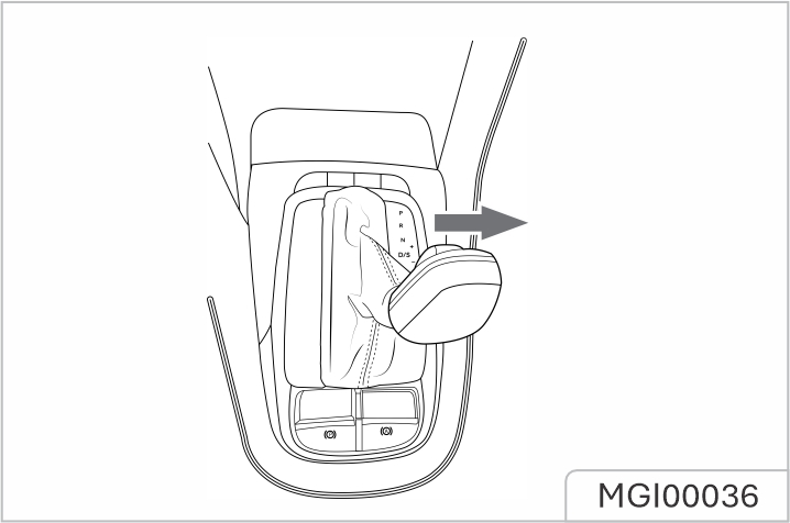
Shift Lever Operation
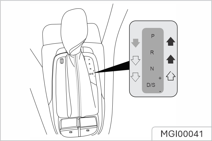
Unless necessary, it is not recommended to press lock button during gear shifting.
During the gear shift, operate the shift lever according to the instructions indicated by the following arrows:
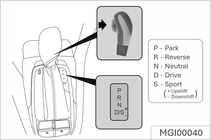
Shift Lever Position
The shift lever must be placed in P position when parked. DO NOT move the gear shift lever into P or R from D whilst driving, this will cause severe transmission damage or cause an accident.
P Park
When the shift lever is in this position, the transmission will be mechanically locked. Use this gear only when the vehicle is stationary and the parking brake is applied.
When the vehicle is parking on a hill, press the brake pedal and apply the parking brake first and then select P gear.
R Reverse
Select this gear only when the vehicle is stationary and the engine is running at idle speed.
N Neutral
Select this gear when the vehicle is stationary and the engine is running at idle speed for a short time (for example, waiting for traic lights).
D Drive
This is used for normal driving and will allow automatic selection of 6 gears depending on vehicle speed and accelerator position.
S Sport
Mode Select this mode when a more sporty acceleration performance is required.
+ Upshift
Whilst in Manual mode, upshift the transmission to the next available high gear.
- Downshift
Whilst in Manual mode, downshift the transmission to the next available low gear.
Gearshift Speed
Selecting D will allow the transmission controller to carry out gearshifts taking in consideration of a number of factors including engine speed, vehicle speed and accelerator position. Light accelerator pedal application will result in a gearchange at low speeds, larger pedal applications will result in gearchanges at higher speeds.
Kick-down
The drive wheels may skid when kick-down is activated on road surfaces with low adhesion, this may lead to the vehicle sliding out of control.
With D gear selected, pressing the accelerator pedal all the way down in one motion (also known as Kickdown) will provide better acceleration performance during overtaking. Under certain conditions, it will allow the transmission to shift to a lower gear immediately, and provide fast acceleration. Once the accelerator pedal is released, it will resume to a suitable normal high gear (based on the vehicle speed and the position of the accelerator pedal).
In cases where a short stop on a hill is required, such as a traic jam, DO NOT momentarily apply the accelerator to prevent “roll back”. This could cause the transmission to overheat and result in damage.
Hill Start
In cases of a hill start, where the vehicle has been stationary for some time, the foot brake has been released and the electronic parking brake applied, the starting assist function of the electronic parking brake (EPB) can be used to prevent the vehicle from rolling backwards. With the seat belt safely fastened, press the foot brake, apply the electronic parking brake system, and select the desired gear (D/R/S), then release the foot brake; press the accelerator pedal to engage vehicle drive, the electronic parking brake system will automatically be deactivated. Models fitted with Hill Hold Control can use this function to assist hill starts. For details on hill hold control system, please refer to “Foot Brake” of “Brake System” section.
The assistance of these functions cannot defy the laws of physics. DO NOT drive the vehicle beyond its physical limitations, loss of control will still occur.
Downhill Driving
Repeated application of the footbrake may result in the brakes becoming overheated. This will cause a reduction in braking performance and may even result in brake failure.
If driving down a hill for long distances, it is advised to move the gear shift lever to the right and select the Manual mode. This allows manual gear selection. Use a lower gear selection to aid the slowing of the vehicle and thus avoiding overuse of the brakes. If a threshold is reached, the vehicle will automatically shift up, in these cases use of the brakes to slow the vehicle is necessary, at the same time re-select the lower gear
When the START/STOP Switch is on and the brake pedal is pressed, if the shift lever cannot be moved out of P gear, turn o the START/ STOP Switch, and apply the EPB. Insert the key or a proper tool into the hole on the upper left corner of the gear shift panel, press the inner P gear emergency unlock button, move the shift lever to N gear simultaneously. Take out the key or the proper tool, start the engine and shift to the required gear
DO NOT shift the lever back to P gear with the P gear emergency unlock button pressed, or the P gear emergency unlock mechanism may be damaged.
If this occurs, please contact the JSW MG Authorised Service Center as soon as possible.
Economy Mode
Selecting D automatically places the vehicle in the Economy Mode. The information centre display will show “D”. Economy Mode provides optimum fuel consumption and emissions.
Sport Mode
Once D is selected, move the shift lever to the right to select S and enable the Sport Mode (the gear displayed in information centre changes to “S”). Under Sport Mode, the transmission upshifts later, so as to make full use of the power reserves of the engine. When better acceleration is required, please select the Sport Mode, but please note that the fuel consumption will be increased when driving in Sport Mode. To exit Sport Mode, move the shift lever to the left back into D position.
Cruise Control Mode *
With the cruise control function enabled, the transmission will switch to the relevant gear for the vehicle speed automatically, thereby avoiding frequent gear shifts when the system needs to maintain a constant speed.
Manual Mode
With Sport Mode selected, move the shift lever toward “+” or “-”, this will enable Manual Mode. The gear displayed in the information centre will indicate current gear with a single number (1~6).
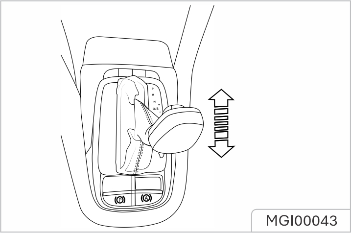
Move the shift lever toward “+” direction to upshift to next available high gear, move toward “-” direction to downshift to next available low gear. With Manual Mode selected, if the driver makes an unreasonable gear selection, requests an upshift during low engine speeds, or requests a downshift during high engine speeds, the transmission will not respond and will remain in the current gear. If the vehicle is driven and the engine speed falls below a preset threshold in certain gears, the transmission will automatically shift down to the next gear to avoid engine stalling; when the vehicle accelerates, if the engine speed exceeds a preset limit, the transmission will automatically shift up to the next gear to protect the engine. To return to Sport Mode or any other modes, shift the lever across to the left and select D.
Automatic Transmission Failure
If the automatic transmission develops a problem, the engine emission malfunction indicator lamp in the instrument pack will illuminate or the message centre will display “EP”. Some “failure modes” will cause the transmission to enter “Limp Mode”, during this time only certain gear positions can be selected and/or work, for example, R gear may not be selectable. If a serious functional failure occurs the vehicle cannot be driven, please consult the JSW MG Authorised Service Center immediately
When the vehicle is in 'Limp Mode', manual gear selection functions are disabled and therefore not available.
Shift lever
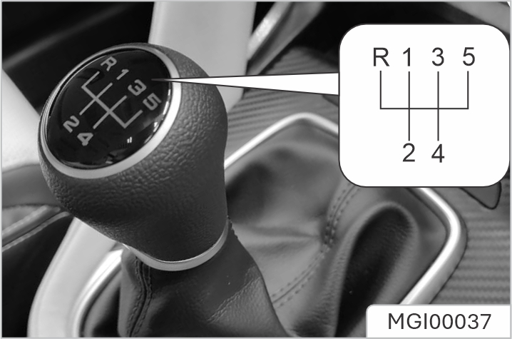
The manual transmission is a 5- speed transmission with 6 gears, which are: 1st, 2nd, 3rd, 4th, 5th, R (Reverse) respectively.
Precautions while driving:
When selecting Reverse gear, you must ensure that the vehicle is completely in stationery, wait for a moment and then fully press the clutch pedal, from the N position, press the lever down and push it leftward, then push it forward into the R position, slowly release the clutch pedal to complete the gear shift.
In order to guarantee the smooth driving and good fuel economy of the vehicle, please shift at an appropriate time, and never allow the tachometer pointer to remain in the red sector for prolonged periods, otherwise the engine may be damaged.
The following information is very important, please read carefully before use:
The automatic transmission is a continuously variable transmission.
The figure or letter in the message centre shows the selected gear.
A lock button with spring located in the gear lever, is used to prevent mistakenly selecting P (Park) or R (Reverse) whilst the gear lever is in other positions.
Shift Lever Operation
Unless necessary, it is not recommended to press lock button during gear shift.
During the gear shift, operate the shift lever according to the instructions indicated by the following arrows:
Shift Lever Position
The shift lever must be placed in P position when parking. During driving, do not switch the shift lever between D and R or switch to P position, otherwise the severe damage to automatic transmission or dangerous accident may occur.
P Park
When the shift lever is in this gear, the transmission will be locked. Use this gear only when the vehicle is stationary and the EPB is applied.
When the vehicle is parking on a hill, press the brake pedal and apply the EPB first and then select P.
R Reverse
Select this gear only when the vehicle is stationary.
N Neutral
Select this gear when the vehicle is stationary and the engine is running at idle speed for a short time (for example, waiting for traic lights).
D Drive
This is used for normal driving and will allow automatic selection of Drive gear depending on vehicle speed and accelerator pedal position.
S Sport
Select this mode when better acceleration performance is required.
+ Upshift
Under manual mode, upshift the transmission to the next available high gear.
- Downshift
Under manual mode, downshift the transmission to the next available low gear.
Gearshift Speed
With D or S gear selected, the speed at one gear varies depending on the accelerator pedal position: a smaller throttle opening will result in the gear shift at a lower speed, and a larger throttle opening will render the transmission to delay the gear shift action, until the gear shift is completed when the vehicle reaches a higher speed.
Kick-down
The drive wheels may skid when kick-down is activated on road surfaces with low adhesion, this may lead to the vehicle sliding out of control.
With D or S gear selected, pressing the accelerator pedal all the way down in one motion (also known as kick-down) will provide better acceleration performance during overtaking. Under certain conditions, it will allow the transmission to shift to a lower gear immediately, and provide fast acceleration. Once the accelerator pedal is released, it will resume a suitable higher gear (based on the vehicle speed and the position of the accelerator pedal).
In cases where a short stop on a hill is required, such as a traic jam, DO NOT momentarily apply the accelerator to prevent “roll back”. This could cause the automatic transmission t
Hill Start
In case of hill start, the starting aid function of the EPB can be used to prevent from slipping. With the seat belt safely fastened, press the brake pedal, apply the EPB, and engage into the desired gear (D/R/S), then release the brake pedal; press the accelerator pedal for start-o, the EPB will automatically deactivated for starting aid. You can also use the hill hold control function to hill start. For details on hill hold control system, please refer to “Brake System” in this chapter.
The aid of these functions cannot defy the laws of physics. DO NOT drive the vehicle beyond its physical limitations, loss of control will still occur
Downhill Driving
Repeatedly pressing the brake pedal may result in brake overheat, thereby causing the degradation of brake performance or brake failure.
If driving down a hill for long distances, slow down first, and then push the shift lever from D gear to the right and enter into manual mode, then manually engage in low gear. Use a lower gear selection to aid the slowing of the vehicle and thus avoiding over-use of the brakes. For example, when driving down the hill with continuous curves, engage into 2 gear; when driving down the straight hill, engage into 3 gear. If the brake force of engine is insuicient, the speed is increased, the automatic transmission will shift to high gear automatically to avoid the overrunning of the engine, at this time, you need to press the brake pedal immediately and shift to appropriate low gear through manual mode.
When the START/STOP Switch is on and the brake pedal is pressed, if the shift lever cannot be moved out of P gear, turn o the START/STOP Switch, and apply the EPB. Insert the key or a proper tool into the hole on the upper left corner of the gear shift panel, press the inner P gear emergency unlock button, move the shift lever to N gear simultaneously. Take out the key or the proper tool, start the engine and shift to the required gear.
DO NOT shift the lever back to P gear with the P gear emergency unlock button pressed, or the P gear emergency unlock mechanism may be damaged.
If this occurs, please contact the JSW MG Authorised Service Center as soon as possible.
Standard Mode
With the shift lever in D position, the automatic transmission enters into standard mode by default automatically, and the message centre will display “D” gear. The standard mode is used for daily driving.
Sport Mode
With the D position selected, move the shift lever rightwards to S gear to enable the sport mode (“S” is presented on the message centre). In sport mode, the transmission upshifts some time later, so as to make full use of the power reservation of the engine. When better acceleration is required, select sport mode, but please note that the fuel consumption will be increased when driving in sport mode. To cancel sport mode, move the shift lever leftwards to D gear.
Cruise Control Mode*
With the cruise control function enabled, the transmission will switch to the relevant gear for the vehicle speed automatically, thereby avoiding frequent gear shifts when the system needs to maintain a constant speed.
Manual Mode
With sport mode selected, move the shift lever towards “+” or “-” direction, this will enable the manual mode. The gear displayed in the message centre will indicate the current gear with a single number (1~8).
In manual mode, the transmission has 8 simulated gears.
Toggle the shift lever towards “+” direction to upshift to next available high gear; or toggle the shift lever towards “-” direction to downshift to next available low gear. In manual mode, if the driver makes an unreasonable gear selection, such as requests an upshift during low engine speeds, or requests a downshift during high engine speeds, the transmission will not respond and will remain in the current gear.
If the vehicle is driven and the engine speed falls below a preset threshold in certain gears, the transmission will automatically shift down to the next gear to avoid engine stalling; when the vehicle accelerates, if the engine speed increases continuously and exceeds the allowable maximum speed but no upshift request received, the transmission will automatically shift up to the next gear to protect the engine. To return to other modes, move the shift lever leftwards and select D.
Transmission Failure
When the transmission has some faults, the engine emission malfunction indicator lamp in the instrument pack illuminates. When some faults occur, the transmission will enter Limp Mode and the vehicle will only function in some gears; while in individual cases it may fail to reverse. If some severe functional malfunctions occur, the vehicle will be inoperative.
If this happens, seek the JSW MG Authorised Service Center immediately. In Limp Mode, the manual mode is disabled.
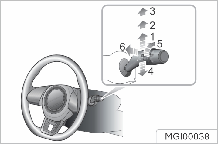
The wipers and washers will only operate with the START/STOP Switch in the ACC/ ON/RUNNING position. Operate the lever to select dierent wipe speeds:
Intermittent Wipe
By pushing the lever up to the Intermittent wipe position (1), the wipers will operate automatically. Turn the switch (5) * to adjust the intermittent wipe frequency. This speed will also change with the vehicle speed. As the vehicle speed
increases, the wiper frequency increases. As the vehicle speed decreases, the wiper frequency decreases. Some models are equipped with a rain sensor fitted to the interior rear view mirror base to detect varying amounts of water on the outside of the windscreen. With automatic wipe, the vehicle will adjust the wiping speed according to the signals provided by rain sensor. Turn the switch (5) to adjust the sensitivity of rain sensor. As the sensitivity increases, the wiping interval decreases.
Immediately operating the wiper one time can be achieved by increasing the sensitivity of rain sensor. If the rain sensor detects a continuous rainwater, the wiper will keep working. When no rain is detected, it is recommended to switch o automatic wipe.
Slow Wipe
By pushing the lever up to the slow wipe position (2), the wipers will operate slowly. Move the lever to reselect the wipe speed.
Fast Wipe
By pushing the lever up to the fast wipe position (3), the wipers will operate fast. Move the lever to reselect the wipe speed.
Single Wipe
Pressing the lever (4) down and releasing will operate a single wipe, if the lever is held down, the wipers will operate until the lever is released.
When the car is stationary, if the bonnet is opened, the front wiper/washer will stop work immediately in some models.
Pulling the lever toward the steering wheel (6) will operate the windscreen washers. After a short delay, the wipers will commence operating in conjunction with the washers.
The wipers continue operating for a further three wipes after the lever is released. After several seconds, there will be a further wipe to remove any fluid draining down the screen.
If the washers fail to deliver the screen wash solution (dirt or ice may have blocked the jets), release the lever immediately. This will prevent the wipers from operating, and the consequent risk of visibility being impaired by dirt smearing across the unwashed windscreen.
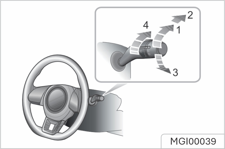
The rear window wiper and washer will only operate with the START/STOP Switch in the ACC/ON/RUNNING position.
Intermittent Wipe
Turn the rear window wiper switch to intermittent wipe (1), the rear window wiper will operate, after 3 consecutive wipes, the wipers will enter into intermittent mode. The time period between the wipes can be increased/decreased via the intermittent wipe frequency adjustment switch (4).
Wash and Wipe
Turn the rear window wiper switch to wash and wipe (2) position and hold, the rear window wiper and washer will operate, the rear window wiper wipes quickly. release the switch allowing it to return to intermittent wipe (1), the rear window washer will stop operating, and the wiper wipes slowly, change the stalk switch position 4 to adjust the wipe speed.
Turn the rear window wiper switch to wash and wipe (3) and hold, the rear window wiper and washer will operate. release the switch allowing it to return to OFF position, the rear window washer will stop operating, and the rear window wiper wipes for 3 times, after several seconds, the wiper will wipe once more to remove the washer fluid on the windscreen.
When the tailgate is opened, rear window wiper operations will be disabled. When the windscreen wipers are switched on, if the shift control lever is moved to, or in the R position, the rear window wiper will operate.
Keep the spare key in a safe place - not in the vehicle! It is recommended that spare keys are not kept on the same key ring, since this may cause interference and prevent correct key recognition and therefore prevent the engine from starting. The key contains delicate electronic components and must be protected from impact and water damage, high temperature and humidity, direct sunlight and the eects of solvents, waxes and abrasive cleaners.
Dierent key kits are provided according to vehicle configurations. One kit includes two smart keys; and the other kit includes two remote keys. They can open all locks. The keys supplied to you have been programmed for the security system on your vehicle. Any key that is not programmed to your vehicle can not start the engine The key only works within a certain range. Its operating range is sometimes influenced by the key battery
condition, physical and geographical factors. For safety consideration, after you lock your vehicle by the key, please recheck if the vehicle is locked.
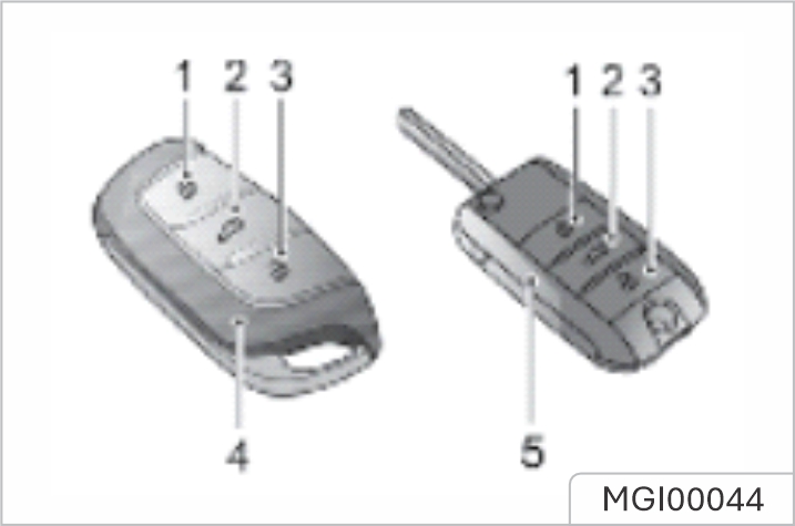
If your key is lost/stolen or broken, a replacement can be obtained from the JSW MG Authorised Service Center. The lost/stolen key can be deactivated. If the lost key is found, JSW MG Authorised Service Center can reactivate it.
Any key made independently outside of JSW MG Authorised Service Center Network may not start the engine, and may aect the safety of your car. To obtain a suitable key replacement, it is recommended that you can consult the JSW MG Authorised Service Center.
The new key cannot be oered to you immediately because it requires programming to the vehicle by the JSW MG Authorised Service Center. When operating your vehicle with the smart key, avoid placing it near the devices with strong radio interference (such as notebook computers and other electronic products), the normal function of the key may be aected.
Please use the picture guide to replace the key battery if any of the following conditions occur:
Smart Key *
Smart key precautions
Keep smart key away from electromagnetic materials that blocks electromagnetic waves to the key surface.
The smart key functionality may be altered or it may cause malfunction under following conditions:
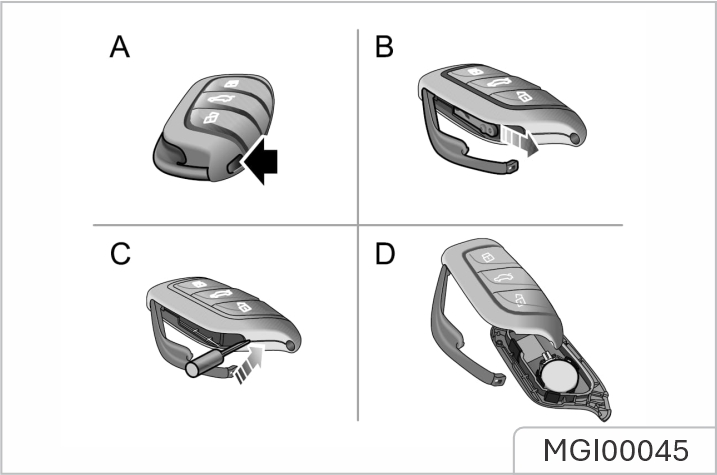
Make sure that the polarity of battery is correct ('+' side facing down). It is recommended to use a CR2032 battery.
Remote key *
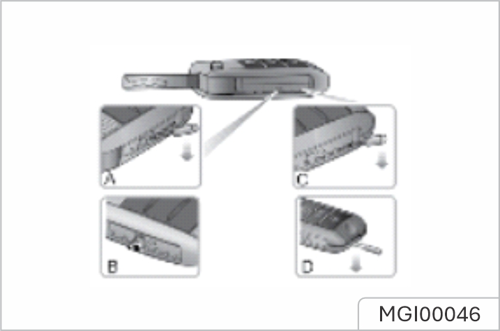
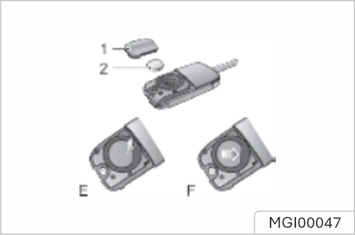
Make sure the polarity is correct (positive side upward). It is recommended to use the CR2032 replacement battery.
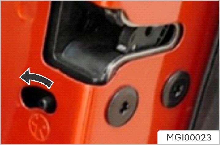
NEVER leave children unsupervised in the vehicle.
Steps for enabling or disabling the child proof locks are as follows:
Your car is fitted with an anti-theft alarm and engine immobilisation system. To ensure maximum safety and operation convenience, we strongly recommend you to carefully read this chapter to fully understand the activation and deactivation of anti-theft systems.
Engine Immobilisation is designed to safeguard the vehicle from theft. Engine Immobilisation can only be deactivated to start the engine by using the matched key.
Engine Immobilisation (Key Start)*
When the matched key is inserted into the START/STOP Switch and the car is started, engine immobilisation is deactivated automatically. When the key is removed from the START/STOP Switch, the vehicle will automatically enable engine immobilisation. When the START/STOP Switch is in the ON position, if the engine immobiliser cannot identify the key inserted into the START/ STOP Switch, the engine immobilisation warning lamp in the instrument pack illuminates. If the engine still can not be started by using the spare key, please contact the JSW MG Authorised Service Center.
Engine Immobilisation (Keyless Start)*
Press the START/STOP Switch on the instrument panel, once a valid key is detected in the vehicle, the immobilisation system will be deactivated automatically. If the message centre displays 'Smart Key Not Detected' or 'Put Key Into Backup Position' or the anti-theft immobiliser system warning lamp illuminates, please put the smart key at the bottom of the centre console cup holder or storage compartment (refer to 'Alternative Starting Procedure' in 'Starting and Stopping Engine' section), or try to use the spare key. If the car can still not be started, please contact the JSW MG Authorised Service Center
Locking and Unlocking
When the vehicle is locked, the indicator lamps flash three times; when it is unlocked, the indicator lamps flash once.
Operation of Door Lock System (Key)
Key Locking
Key Unlocking
If the START/STOP Switch is not placed in ACC or ON/RUNNING position within 15 seconds after the vehicle is unlocked with the mechanical key, the engine immobilisation alarm will be triggered. If no panels are opened within 30 seconds after the vehicle is unlocked by using the remote key, all doors will automatically re-lock
Operation of Door Lock System (Keyless)*
The keyless entry system can lock and unlock the doors and tailgate as long as you carry the smart key and approach to the car.
Operation of Door Lock System (Key)
Key Locking
Key Unlocking
The smart key must be within 1.5 metres of the vehicle for the keyless system to operate correctly.
Keyless Locking
After switching the START/STOP Switch to OFF position and exiting the car, press the door handle button once before moving away
from the car to lock all doors and tailgate (no need to press the lock button on the key). Note, this will also arm the alarm and immobilise the vehicle.
Keyless Unlocking
Press the button on the front door handle once to unlock the car, then pull the door handle to open the door.
When the vehicle is locked, if you are within the smart key range and operate the door handle button, but carry out no further action, after 30 seconds the vehicle will automatically relock itself to remain secure.
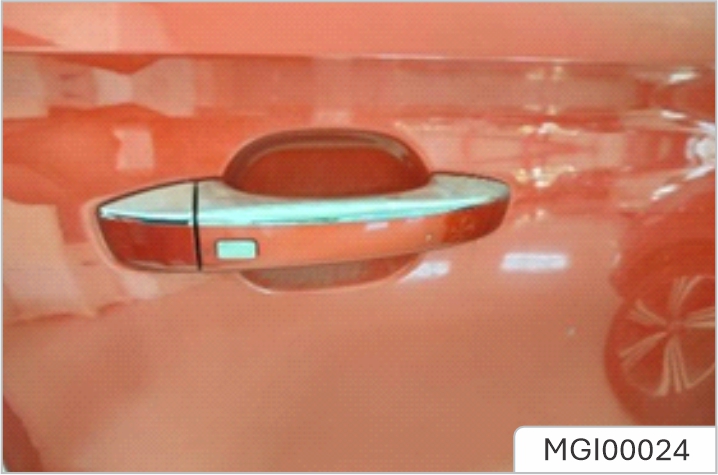
After the door is locked by using the key, press the button on the door handle to unlock the car. If the car cannot be unlocked or locked normally, seek the JSW MG Authorised Service Center.
Mislock
If the driver's door is not fully closed when the smart key lock button is pressed, or the START/STOP Switch has not been switched OFF, the vehicle horn will sound once, indicating a mislock. In this case, none of the doors will lock, the alarm system will not be armed. If the driver's door is closed, the passenger door, bonnet and tailgate are not fully closed, the horn sounds once to indicate mislock when the car undergoes locking operation. However, the 'partial arming' attributes of the security system will enable as much of the system to be armed as possible (all fully closed doors, bonnet or tailgate apertures will be protected, but an open door will not!). The alarm indicator will flash. As soon as the open aperture is closed, the system will automatically revert to an armed state.
Anti-theft Alarm Sounder
If the anti-theft alarm has been triggered, the car horn will sound continuously. Press the UNLOCK button on the key, the anti-theft alarm will be deactivated.
Interior Lock and Unlock Switch
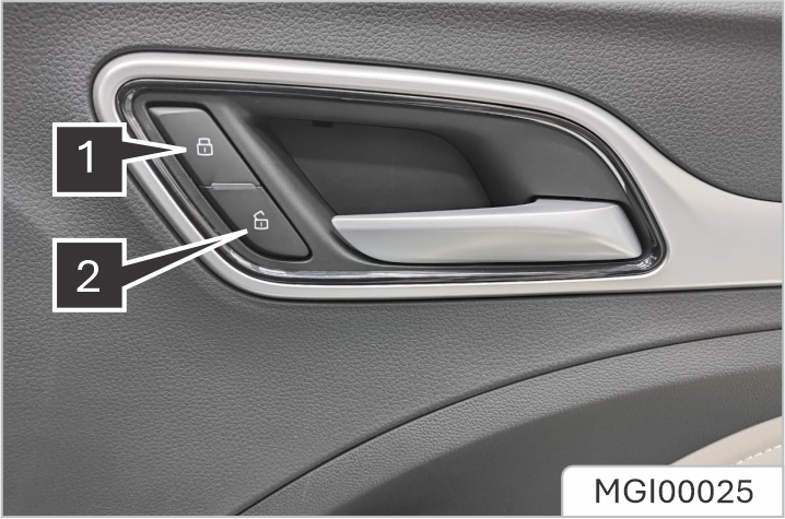
When the anti-theft alarm system is not in operation, press the lock switch (1) to lock all doors; press the unlock switch (2) to unlock all doors.
If the anti-theft alarm system is switched on, pressing the lock/unlock button will not lock/unlock the doors but will trigger the alarm system.
If the doors, bonnet and tailgate are closed, press the interior lock switch. The yellow indicator on the interior lock switch illuminates. If a mislock is caused by non-driver door, tailgate or bonnet, press the interior lock switch. The yellow indicator on the interior lock switch illuminates. Interior Door Handles Use the interior door handle to open the door:
Speed Lock
All the doors will be locked automatically when the road speed exceeds 10 mph (15 km/h).
Automatic Unlock
When the START/STOP Switch is switched to the OFF position, all the doors will be unlocked automatically.
If the tailgate can not be closed due to the type of cargo loaded, be sure to close all windows during driving, select the face distribution mode of the air condition, and set the blower to maximum speed, so as to decrease exhaust fumes entering the vehicle.
Tailgate Open Mode
The tailgate can be opened by using the following 2 methods:
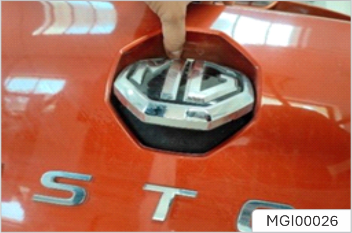
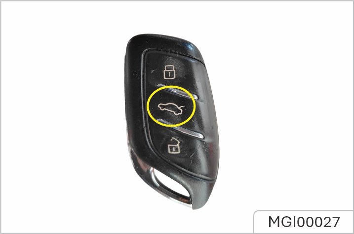
Emergency Tailgate Opening
The emergency tailgate release access is located in the centre of the tailgate trim. Fold the rear seats, dig out the blanking cap with a hand, and insert a small flat-blade screwdriver into the emergency open locking slot to open the tailgate from inside, as shown in the figure.
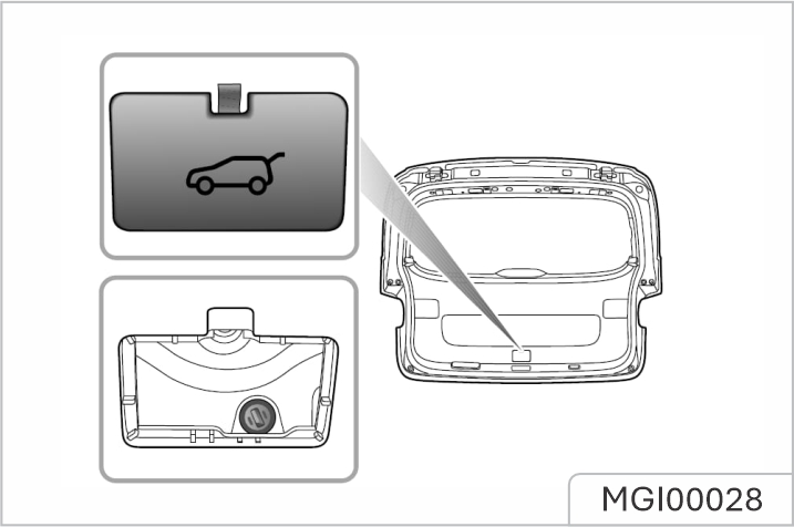
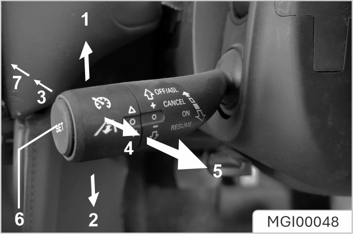
Cruise control enables the driver to maintain a constant road speed without using the accelerator pedal. This is particularly useful for motorway cruising, or for any journey where a constant speed can be maintained for a lengthy period.
Cruise Control System Activation
Cruise control system is operated with a lever located, at the left side of the steering wheel underneath the lighting stalk switch. With the START/STOP Switch in position ON/RUNNING, if the lever switch is in the 'ASL Standby' position (7 in
figure), then the cruise control is OFF. To set the cruise control to 'Standby' pull the lever switch to 'Cruise Standby' (4 in figure), the yellow indicator lamp in the instrument pack will illuminate indicating the system is in 'Cruise Standby' mode. With the system in 'Standby' when the current vehicle speed is above 40km/h (the gear of vehicle with manual transmission should be at 3 or above), press the 'Cruise Set' button (6 in figure). The indicator in the instrument pack will change to green and the cruise control will enter and activated state. The operating range is 40 - 200 km/h. The target speed of the cruise system will be set at the current speed, and the cruise system will take eect. At this time, the cruise control system will maintain the set speed without pressing the accelerator pedal.
The set speed held in the cruise control memory will be cancelled when either the cruise control lever is switched to “ASL Standby” position (figure 7) or the START/STOP Switch turned off.
Target Cruise Speed Adjustment
When the cruise control is active, the 'target speed' can be increased or decreased: Push the lever switch upwards (1 in figure), this will increase the speed. Push the lever switch downwards (2 in figure), this will decrease the speed. Release the lever switch when the desired speed is reached. Push the lever switch upwards or downwards briefly to increase/decrease the vehicle target speed in increments of 1 km/h, then the vehicle will accelerate/decelerate to the new target speed. Pressing the accelerator at any time will override the cruise control and allow acceleration to undertake manoeuvres such as overtaking. Releasing the accelerator will return the vehicle to the set target speed.
Pause / Stand By
Cruise control will be disengaged and set to 'Standby' if:
Resume
If the cruise control remains on after the disengagement, moving the lever switch to 'Cruise Resume' (5 in figure) will reinstate the target speed to the setting prior to disengagement.
The adaptive cruise control system is designed as a comfort system enabling the driver to maintain a constant speed or distance from the car in front. It provides assistance to the driver, it DOES NOT replace any of the drivers responsibilities. When using the adaptive cruise control system, it is important that the driver maintains concentration at ALL times and is prepared to take action. Otherwise, accidents or personal injuries may occur.
The adaptive cruise control system can automatically switch between constant speed cruise and car following cruise depending on whether it can detect a vehicle directly ahead. Constant speed cruise controls the vehicle at a certain speed range. Car following cruise operates by setting the distance between the vehicle and the vehicles directly ahead. When activated if the adaptive cruise control system detects a vehicle in the same lane directly ahead it may accelerate or gently apply braking of the vehicle to maintain the set following distance.
The adaptive cruise control system is designed for highways and roads in good condition. It is recommended not to be used on urban roads and mountain roads.
After following the vehicle ahead to a stop, the driver must observe any local traic laws and ensure that there are no obstacles or other traic participants, such as pedestrians, directly in front of the vehicle before allowing it to pull away and begin to follow the vehicle ahead again. Whilst using the car following cruise function it is strongly recommended that the driver does not touch the accelerator pedal. Any activation of the accelerator will not allow the system to automatically apply the brakes should this be
necessary. DO NOT exit the vehicle when the adaptive cruise control system car following cruise function has stopped the car, or is keeping the car stationary. Before exiting the car the shift control knob should be in the Park position and the START/ STOP Switch in the OFF position. If the adaptive cruise control system has already stopped the vehicle, and the adaptive cruise control function is disabled, turned o or cancelled, the vehicle will no longer stay still, it may move forward or slip backward. When the vehicle is stopped and kept still by the adaptive cruise control system, be sure to be ready to apply the brakes manually. When driving on a bend, the adaptive cruise control may actively reduce the vehicle speed to maintain vehicle stability and safety.
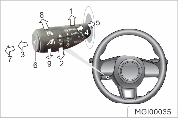
The adaptive cruise control system is operated with a lever switch, which is located under the left side of the steering wheel.
following cruise. An image of your car and the car ahead is displayed in the instrument pack message centre. In this mode the actual speed may be less than the set target speed. Whilst in the car following cruise mode, you can follow the vehicle ahead to a stop. If the parking time is less than a preset time period, your vehicle may automatically pull away to follow the vehicle ahead, or you need reactivate the adaptive cruise control system using the method displayed.
Manual deactivation of either the Traction Control System (TCS) or Stability Control System (SCS) will inhibit the operation of the adaptive cruise control system.
When the adaptive cruise control system is activated:
If the vehicle ahead continually makes hard acceleration or deceleration manoeuvres the adaptive cruise control may not be able accurately maintain the required distance between vehicles. It is important that the driver always concentrates and pay attention to the current vehicle position and situation in case they need to make a braking or avoidance manoeuvre.
When the adaptive cruise control system is activated, rotate the switch on the end of the lever upward (8) or downward (9) to adjust the following distance, you are able to toggle between 3 distance settings which are displayed in the message centre in the instrument pack. Always select an appropriate following distance that is relative to the current speed of your vehicle and the vehicle you are following, the greater the speed, the further the distance. ALWAYS consider current traic, road and weather conditions when making your selection.
When the adaptive cruise control system is activated, move the lever switch to the 'Cancel' position (3), and the system will exit to the Standby mode.
In the following situations, the adaptive cruise control system may be automatically deactivated, this transfers full control of the vehicle to the driver.
If following the vehicle ahead to a stop with the adaptive cruise control system enabled, if any of the following conditions occur whilst the vehicle is in a stopped state, the EPB will automatically be applied:
If the driver has cause to use the accelerator pedal when the adaptive cruise control system is activated, the vehicle will remain in Cruise mode while the vehicle speed increases. When the accelerator pedal is released, the adaptive cruise control system will resume to operate at previously set cruise speed.
If the adaptive cruise control system has reverted to, or been switched to, the Standby mode it can be reactivated by moving the lever switch to the 'Resume' position (5). The target cruise speed will automatically be set to the target speed before exiting the adaptive cruise control system.
If the lever switch is moved to the 'OFF' position (7) or the vehicle START/STOP Switch is switched to the OFF position, the system may clear the adaptive cruise control set speed in the memory.
The adaptive cruise control system has it's limitations. Listed below are some conditions that may be beyond the safe operating limits. The driver should maintain control of the vehicle and must remain alert at all times. They should pay special attention to the traic conditions and surroundings, select the appropriate speed and be ready to take any required actions.
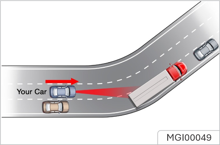
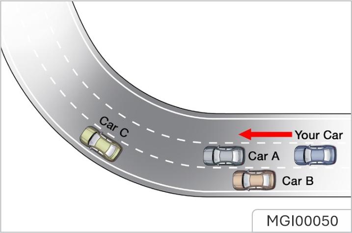
When turning at an intersection or following a vehicle into, or out of a curve, the adaptive cruise control system may be unable to detect the vehicle ahead, even if it is in the same lane, it is possible the system may detect a vehicle in another lane.
Do not use the adaptive cruise control system on entrance/exit ramps or sharp bends.
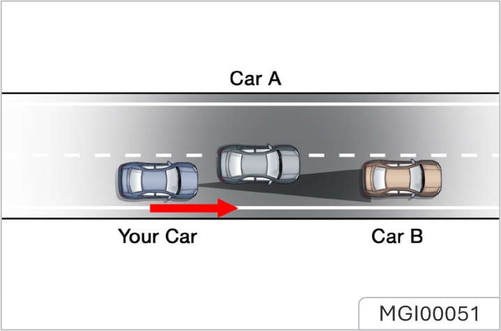
If the vehicle ahead changes lanes, but does not drive into the lane completely, the adaptive cruise control system may be unable to detect the vehicle. If the vehicle ahead changes lanes, but does not exit the lane completely, the adaptive cruise control system may determine that the vehicle ahead has exited the lane and accelerate to any preset speed.
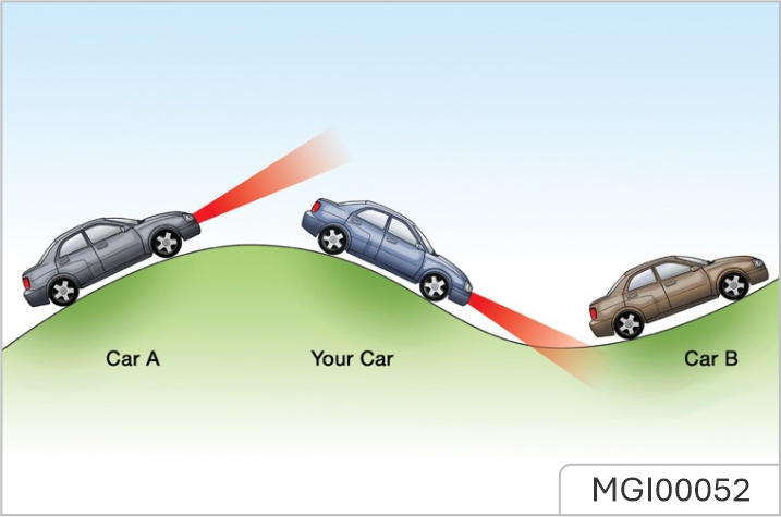
When driving on uneven roads that may include steep climbs or dips please DO NOT use the adaptive cruise control system.
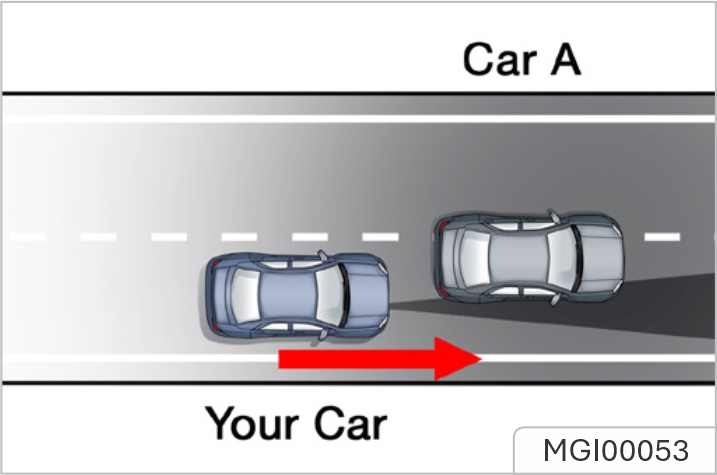
When driving behind a vehicle that is only partially overlapping your vehicle, 'A' in the graphic, the adaptive cruise control system may be unable to detect anything.
Please DO NOT use the adaptive cruise control system in the following situations:
The driving assist system can detect the road and environmental information ahead of the vehicle by utilising a front view camera and a front detection radar under certain conditions. This information is used to relay warning messages or provide assistance to help the driver in controlling the vehicle in a safer and more reliable manner. The front view camera is located in the interior rearview mirror base cover, the front detection radar is located at the low
The front view camera will require recalibration operations:
The calibration of front view camera requires professional knowledge and tools. If calibration is required, please seek the JSW MG Authorised Service Center.
Obstruction of the front view camera
On occasion the front view camera view may become obstructed by foreign objects or stains on the glass. In these cases a prompt message will appear in the information centre. Please wipe or clean immediately.
In the following situations, the detection performance of front view camera will be aected:
Front radar performance will be eected in the following situations:
Experiencing any of these could cause the function of the front detection radar to be eected.
Any snow that gathers on the front radar may be removed using a soft brush, and any ice should be removed using a propriety deicing spray. Avoid any collision or contact with the front radar module, this may cause misalignment.
The intelligent speed limit is an auxiliary function, it may display an incorrect speed limit value or no speed limit value in the instrument pack due to various factors. As a result, the vehicle speed is not restricted within the correct range. The driver still needs to observe the speed limit of the road traic, and speeding is strictly prohibited. The front view camera cannot recognise speed limit signs painted on the road surface. The driver MUST observe these speed limits and adjust the their speed accordingly.
![]() The speed assist
system settings are
available via the
infotainment system.
When the adaptive cruise control
system is OFF, the following three
functions can be selected:
The speed assist
system settings are
available via the
infotainment system.
When the adaptive cruise control
system is OFF, the following three
functions can be selected:
visual warning will be available during the intervention.
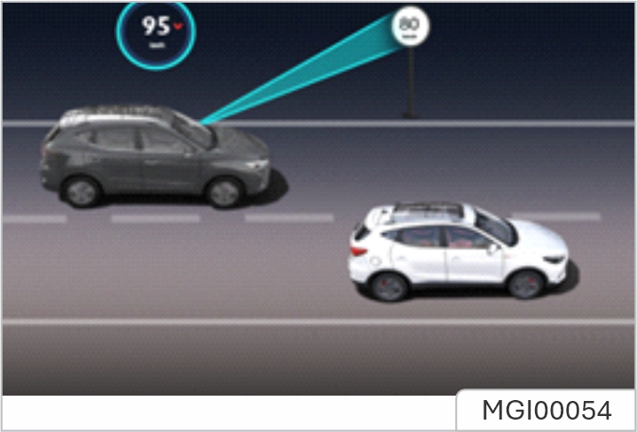
Speed assist system setting
The operating interface for the speed assistance system is located in the infotainment display. Enter the vehicle setting interface to locate the driving assist option, scroll across the page to find the setting interface for the speed assist system:
Speed settings of manual speed assist:
After the manual speed assist function is enabled, the speed limit value can be set by using the adaptive cruise control lever as follows:

![]() When the speed warning
function or intelligent speed assist
function is enabled, the system
indicator lamp on the instrument
pack illuminates green. When the
manual speed assist function is
enabled, the system indicator lamp
on the instrument pack illuminates
yellow. When the function is
activated by pressing the SET button
on the adaptive cruise control lever,
the system indicator lamp
illuminates green. If the speed
assist system detects a fault or
failure, the indicator lamp will flash
yellow then extinguish.
When the speed warning
function or intelligent speed assist
function is enabled, the system
indicator lamp on the instrument
pack illuminates green. When the
manual speed assist function is
enabled, the system indicator lamp
on the instrument pack illuminates
yellow. When the function is
activated by pressing the SET button
on the adaptive cruise control lever,
the system indicator lamp
illuminates green. If the speed
assist system detects a fault or
failure, the indicator lamp will flash
yellow then extinguish.
![]() When the speed warning
function or intelligent speed assist
function is enabled, the speed limit
value indication illuminates.
The “NNN” is displayed as “—”.
When the vehicle passes the first
speed limit sign identified, the
speed limit indication displays the
real-time speed limit value
When the speed warning
function or intelligent speed assist
function is enabled, the speed limit
value indication illuminates.
The “NNN” is displayed as “—”.
When the vehicle passes the first
speed limit sign identified, the
speed limit indication displays the
real-time speed limit value
When the vehicle needs to change lane, make a turn or turn around at an intersection and the driver uses an indicator in advance and slows down, the original speed limit value on the instrument pack will be reset and displayed as “—” until a new speed limit sign is detected. If the conditions are not met, the original speed limit value will be maintained and not be reset. The driver MUST observe the speed limits and adjust the speed accordingly.
When the manual speed assist function is enabled, the speed limit value indication illuminates. The “NNN” is displayed as “—”. Press the SET button to activate the manual speed assist function, The “NNN” is displayed as 30km/h or the current actual speed. Move the adaptive cruise control lever up and down to adjust the target speed limit value. The driver can directly switch o, or temporarily suspend the speed assist system by carry out the following actions:
The speed limit information function and intelligent speed limit function may be impaired in the following situations:
The camera may not correctly recognise speed limit signs during poor lighting conditions, bad weather, non standardized or sheltered speed limit signs or the camera's own restrictions which include the recognition of similar signs (e.g., recognise a weight limit sign as a speed limit sign, or recognise a minimum speed sign as the maximum speed sign).
The lane assist system is an auxiliary system that provides assistance to the driver. It does NOT remove the responsibility of safe driving from the driver. When choosing to use the lane assist system, the driver MUST always pay attention to the surroundings, hold the steering wheel and be prepared to make manoeuvres at any time. Failure to maintain overall control of the vehicle may result in an accident or personal injury. The lane assist system does not always recognise the lane lines. Sometimes poor road surfaces, certain road structures or objects may be mistaken for lane lines. When such situations occur, the lane assist system must be immediately turned off.
The lane assist system switch is located in the infotainment display. Enter the corresponding interface for driving assistance to turn the system ON/OFF, and make mode selection.
Lane Departure Warning
The system uses the front view camera to detect the lane lines ahead of the vehicle. The system will be activated when the following detection conditions are met:
Lane Departure Prevention
The system uses the front view camera to detect the lane lines ahead of the vehicle. The system will be activated when the following detection conditions are met:
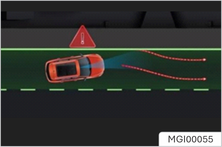
Lane Keep Assist
The system uses the front view camera to detect the lane lines ahead of the vehicle. The system will be activated when the following detection conditions are met:
The system will always attempt to maintain the vehicle position in the centre of the lane by using corrective steering interventions. If the vehicle deviates from the lane lines too much, the system will activate the alert function. The function will automatically exit when the vehicle speed drops below 55 km/h. In the absence of a steering input from the driver for a certain period of time, the system will provide warnings.
The lane assist system will be impaired or ineective in the following conditions:
It is recommended to turn o the lane assist system in the following situations:
The driver remains responsible for the safety of the entire driving process, even if the vehicle is equipped with a forward collision system. The driver MUST pay full attention and drive carefully. As with all the driver assist systems, the forward collision system cannot prevent accidents or avoid collisions in all situations. The driver MUST always remain in control to avoid accidents or emergency situations. Emergency braking whilst under the control of the forward collision system may cause injuries to the passengers. Therefore, drive carefully and all passengers MUST wear seat belts at all times. Ensure the forward collision system or vehicle power system is switched o when being towed. If the forward collision system is enabled when the vehicle is being towed, adverse eects may aect the safety of your vehicle, the towing vehicle and the people around. To avoid the occurrence of accidents, never specially test the functions of the forward collision system.
The forward collision system switch is located in the infotainment display. Enter the corresponding interface for driving assistance to turn the system ON/OFF, and make mode selection.
Alert
When the system detects that there is a risk of collision between the vehicle and the vehicle in front in the same lane, warnings will be provided to prompt the driver to slow down in time and keep a relatively safe distance from the vehicle ahead.
Emergency braking
When the system detects that there is a risk of collision between the vehicle and the vehicle directly in front of the vehicle, the brake system will automatically intervene to decelerate the vehicle, so as to avoid collision accidents or mitigate damage from collision accidents. If the vehicle is braked and stopped under the system control, it will remain stationary for a short time. Full control of the vehicle will then be returned to the driver
Pedestrian auto emergency braking
When the system detects that there is a risk of collision between the vehicle and the mobile pedestrian directly in front of the vehicle, the brake system will automatically intervene to decelerate the vehicle, so as to avoid collision accidents or mitigate damage from collision accidents. If the vehicle is braked and stopped under the system control, it will remain stationary for a short time. Full control of the vehicle will then be returned to the driver.
The system will only slow down the vehicle automatically if the following conditions are met:
In some cases, the driver may not have anticipated any braking intervention and does not want to apply the brakes whilst the forward collision system is braking heavily, the driver can temporarily cancel this operation by heavily pressing the accelerator pedal after ensuring that it is safe to do so.
The operation of the forward collision system may be impaired or ineective in the following situations:
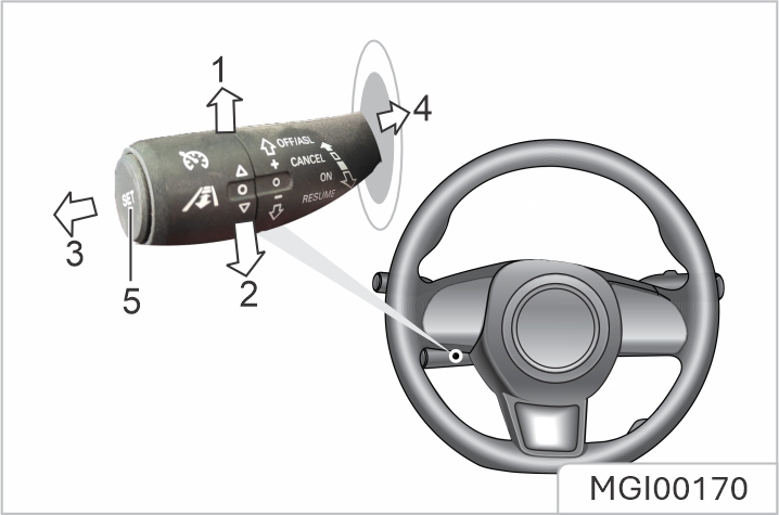
The Active Speed Limit (ASL) system is designed to control the vehicle speed keeping it below a speed set by the driver. The ASL system shares the same lever switch as the cruise control system, located to the left of the steering wheel below the indicator stalk. The switch can be toggled between both functions, however only one function can operate at any one time
The desired target speed of the ASL system is displayed in the instrument information cluster. With the START/STOP Switch in position ON/RUNNING and the lever switch in “ASL Standby” (3 in figure), the ASL function is in standby mode. Pressing the “Set” button (5 in figure) will activate the ASL system. When activated and vehicle speed is less than or equal to 30 km/h, then the target speed limit value will be set at 30 km/h by default. When activated and vehicle speed is higher than 30 km/h, then the current vehicle speed will be set as the target speed limit value. Firstly, the target speed limit value will be rounded when the lever switch is moved upwards or downwards. Then, the target speed limit value will be increased or decreased by 5 km/h every time the lever switch is briefly moved upwards or downwards. Move the lever upwards or downwards and hold, the target speed limit value will change continuously in units of 5km/h. The range of target speed adjustment is 30 - 200km/h.
When activated if the vehicle speed is greater than the user inputted target speed the system will begin to slow the vehicle to the inputted target. When ASL is active, pressed the accelerator pedal fully (eg: overtaking) can make the vehicle speed increased. When released the pedal, vehicle speed will subject to the target speed limit value.
When ASL is active, to suspend the feature press the “Set” button (5 in figure) and the ASL system will exit to the standby state.
If the system has been placed in a standby state with a retained target speed the system can be reactivated to the previously stored target speed by pressing the “Set” button (5 in figure).
When ASL is suspended, if the accelerator pedal is fully depressed (eg: overtaking), the system can not be reactivated.
Pull the lever switch to “Cruise Standby” position (4 in figure), ASL system will exit.
ASL system brakes the vehicle relied on the engine, which has limited braking capacity. ASL is not a substitute for the brakes. In case of steep slopes and other needs to brake quickly, please press the brake pedal to brake the vehicle.
The purpose of the parking aid is to assist the driver in reversing! The sensors may not be able to detect obstacles of certain type, e.g. narrow posts or small objects no more than a few inches wide, small objects close to the ground, objects above the tailgate and some objects with non-reflective surfaces. Keep the sensors free from dirt, ice and snow. If deposits build up on the surface of the sensors, their performance may be impaired. When washing the car, avoid aiming high pressure water jets directly at the sensors from close range.
Rear Parking Aid
The ultrasonic sensors in the rear bumper monitor the area behind the vehicle to search for obstacles. If any obstacle is detected, the system will calculate its distance from the rear of the vehicle and communicates the message to the driver by sounding warning chimes.
Parking Aid in Operation
The rear parking aid is enabled automatically when reverse is selected, it is switched o as soon as reverse is disengaged. A short beep is given by the parking aid within 1 second after selecting reverse to indicate that the system is operating normally.
If a longer, higher pitched sound is emitted for 3 seconds when reverse is selected this indicates a fault in the system. In this case seek assistance from your JSW MG Authorised Service Center.
With the parking aid enabled, when obstacles are detected, the system will give sounds in dierent frequencies (there might be blind areas)
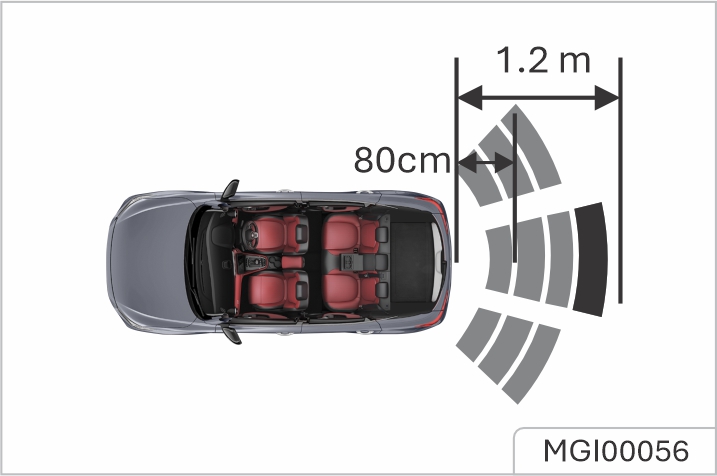
The purpose of the parking camera system is to assist the driver in reversing! The camera has limited field of view and cannot detect obstacles outside the field of view.
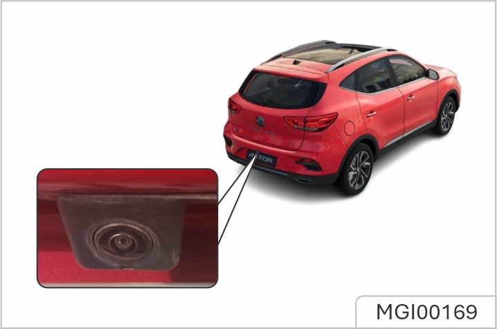
The parking camera is fitted between left and right license plate lamps. When the reverse is selected, the camera will display an image of what is directly behind the car in the entertainment display, and the system supports the indication of distance from obstacles to vehicles.
The purpose of the 360 panoramic imaging system is to assist the driver during reversing! The cameras have a limited field of view and cannot detect obstructions outside the field of view. Although the entertainment display can provide highdefinition images around the vehicle, please still pay attention to the current actual road conditions for your driving safety. Make sure the exterior rear-view mirror is deployed, when using the 360 panoramic imaging system.
With the 360 panoramic imaging system working, the display interface will show a 360° panoramic image of the vehicle to facilitate the observation of the surrounding environment. you are able to touch dierent areas around the vehicle to check images from dierent angles of view. The 360 panoramic imaging system can be accessed in the following ways:
When the shift lever is placed in forward gear position, in no case can 360 panoramic imaging system be enabled as long as the vehicle speed exceeds or equals to 15 km/h.
The eective recognition capabilities of the rear sensors can be limited by objects such as roadside buildings, guardrails, changes in pitch angle of the car due to heavy loading, road conditions such as bends or bumps or weather conditions such as snow and ice etc. Any of the above may trigger a false alarm. The rear driver assist system may not provide adequate warning of very fast approaching vehicles or operate correctly on tight curves of 500m radius or less. The rear driver assist system will not operate correctly whilst towing a trailer or caravan. The system has limitations and may not be able to warn of vehicles approaching at high speeds. The rear driver assistance function is only an aid, it is NOT a substitute for the attention of the driver. The driver must always remain in control, observe the surroundings and drive safely. The
correct operation of the rear sensors will be compromised if they are misaligned due to accident damage. This may cause the system to automatically shutdown. To ensure that the radar sensors work correctly, the rear bumper should be kept free of snow and ice and must not be covered. Use of non recommended materials or paint on rear bumper repairs may have a detrimental eect on the operation of the rear sensors. Please only use recommended materials.
The rear driver assistance system includes blind spot detection (BSD), lane change assist (LCA), and rear cross traic alert (RCTA) functions. The rear driver assistance modules are mounted at the rear of the vehicle on each side, they can assist in detecting vehicles behind or to the side of your vehicle. The warning lamps to support this system are located within the LH and RH door mirror glasses, they will illuminate or flash to warn of an approaching object or car to assist you in manoeuvring the car safely.
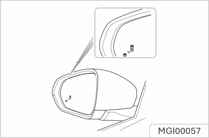
The rear driver assist system function and sub system switches can be accessed via the infotainment screen. Select ON/OFF to activate/deactivate the system.
The detection area, collision time threshold value and vehicle speed provided in the system function description are just for your reference.
When the vehicle is driving forward, the system will monitor the motor vehicles located in the blind zones of the left and right exterior mirrors. When the conditions for activating the blind spot detection function are met, the warning lamps in the corresponding mirror will illuminate. Subsequent operation of the relevant indicator will cause the warning lamp in the mirror to flash to remind the driver of an approaching vehicle.
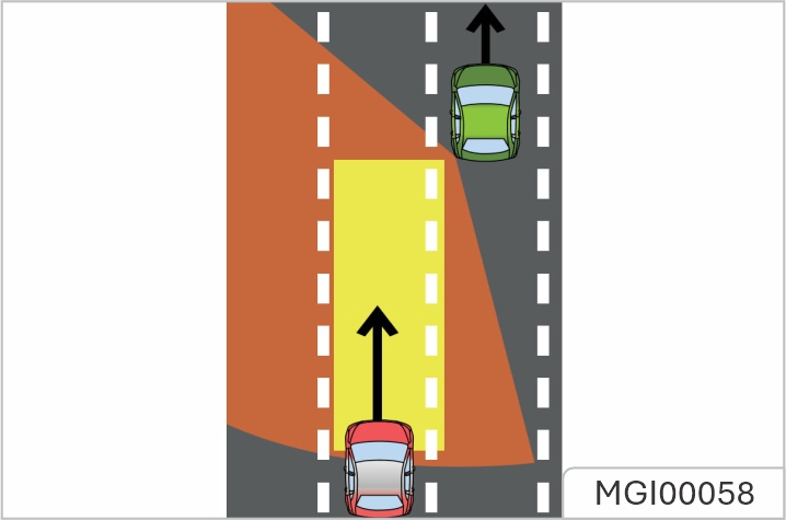
The conditions for activating the blind spot detection function include:
The warning lamps will not illuminate whilst you are overtaking another vehicle and your speed is greater than that of the vehicle you are passing, even though it is in the blind zone.
When the vehicle is driving forward, the system will monitor the motor vehicles approaching rapidly in the adjacent lanes. When the conditions for activating the lane change assist function are met, the warning lamps in the corresponding mirror will illuminate, once the indicators are activated, the warning lamps will flash to warn the driver of an approaching vehicle. This aims to help avoid collisions when changing lanes.
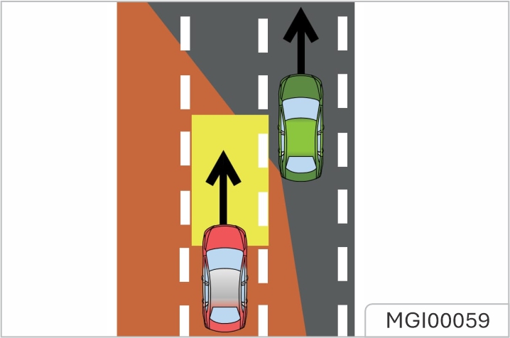
The conditions for activating the lane change assist function include:
When the vehicle is reversing, the system will monitor vehicles approaching from the left and right rear. When the conditions form activating RCTA function are met, the warning lamps in the mirrors on the corresponding side will illuminate, parking information will be displayed in the infotainment screen to alert the driver to the situation.
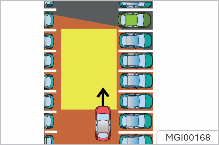
The conditions for activating the rear cross traic alert function include:
can not replace routine maintenance and checks of tyre condition and pressures. Using equipment that transmits on frequencies similar to that of the TPMS may interfere with the operation of the Tyre Pressure Monitoring System, this may illuminate a warning or register a temporary fault.
TPMS only warns of low tyre pressures, it does not re-inflate the tyre.
TPMS uses pressure sensors built into tyre valves to continuously monitor pressure and transmit data to the ECU inside the vehicle using RF signals. If it deduces that the pressure of that tyre has fallen below the predefined limit of the system, the warning light in the instrument pack will illuminate (always yellow). For more information, please refer to 'Instrument Pack' in 'Instruments and Controls' section. TPMS can remind you of low tyre pressure, but it can not replace normal tyre maintenance. For tyre maintenance, please refer to 'Tyres' in 'Maintenance' chapter.
![]() If the TPMS malfunction
indicator lamp illuminates, and the
warning message “XX Tyre Pressure
Low” is accompanied displayed, it
is advised that you please stop the
car as soon as possible, check the
tyre pressure and inflate the tyre to
correct pressure value. Driving with
under-inflated tyres, the tyre will
overheat and cause tyre fault. Using
under-inflated tyres increase more
energy consumption and result in
shorter tread life, and may aect
vehicle handling and braking
performance. Always check/adjust
tyre pressures when they are cold.
The tyre pressure label attached to
the vehicle indicates the correct
amount of tyre inflation required for
your vehicle when the tyre is cold.
If the TPMS malfunction
indicator lamp illuminates, and the
warning message “XX Tyre Pressure
Low” is accompanied displayed, it
is advised that you please stop the
car as soon as possible, check the
tyre pressure and inflate the tyre to
correct pressure value. Driving with
under-inflated tyres, the tyre will
overheat and cause tyre fault. Using
under-inflated tyres increase more
energy consumption and result in
shorter tread life, and may aect
vehicle handling and braking
performance. Always check/adjust
tyre pressures when they are cold.
The tyre pressure label attached to
the vehicle indicates the correct
amount of tyre inflation required for
your vehicle when the tyre is cold.
TPMS Self-learning
When replacing a TPMS sensor and receiver, or performing tyre rotation, TPMS self learning is required, please consult the JSW MG Authorised Service Center for details
DO NOT exceed the gross vehicle weight or the permitted front and rear axle loads. Failure may result in vehicle damage or serious injury.
Ensure that the rear seat backrests are securely latched in the upright position when loads are carried in the load space behind the seats. If the boot lid (or tailgate) can not be closed due to the type of cargo loaded, be sure to close all windows during driving, select the face distribution mode of the air condition, and set the blower to maximum speed, so as to decrease exhaust fumes entering the vehicle.
When luggage carried in the boot, always ensure heavy items are placed as low and as far forward as possible, so as to avoid the cargo shift in the event of an accident or sudden stop. Drive carefully and avoid emergency braking or
maneuvers when large or heavy items are carried. Driving with the boot lid (or tailgate) open is very dangerous. If the load being carried requires the boot lid (or tailgate) to be open, please ensure the cargo and the boot lid (or tailgate) are suitably secured and every measure is taken to prevent exhaust fumes entering the vehicle.
Traic regulations must be observed when loading cargo, if the cargo extrudes the loadspace, appropriate warning measures must be taken to warn other road users.
DO NOT carry unsecured equipment, tools or luggage that could move, causing personal injury in the event of an accident, emergency braking or hard acceleration. DO NOT obstruct the driver and passengers to keep right sitting posture and observation with loads
Folding the rear seats can increase luggage space, refer to “Rear Seat” in “Seats and Restraints” chapter. When cargo is loaded in the vehicle, place it at a position as low as possible and ensure that it is tightly secured, so as to avoid personal injury caused by cargo movement when traic accidents or emergency brakes occur. If the cargo has to be put on a seat, no one is allowed to sit on that seat
Objects viewed in door mirrors may appear further away than they actually are.
Electric Door Mirror Glass Adjustment
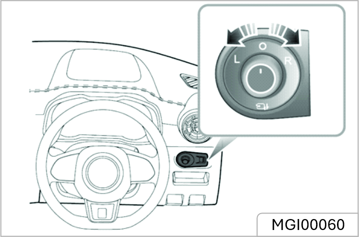
Heating Elements*
The door mirrors have integral heating elements which disperse ice or mist from the glass. The heating elements operate while the Heated Rear Window is switched on.
The heating elements of rear window and mirror will only work when the engine is running.
Mirror Folding
The mirrors can be folded back towards the side windows into a 'park' position to enable the car to negotiate narrow openings and avoid collisions
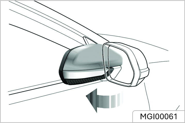
Manual Folding of Door Mirror*
For vehicles not fitted with the electric door mirror fold option, the exterior mirrors can only be folded backwards manually.
Electric Folding of Door Mirror *
For vehicles fitted with electric door mirror folding, rotate the knob to the middle position and push the knob down. The door mirrors will be folded automatically. Pushing the knob downwards again will return the mirrors to their original position. Operating the key fob lock/unlock buttons will fold/unfold the door mirrors.
Electrical folding door mirrors that have been moved from their positions by manual or accidental means must be reset by operating the knob to complete fold and deployment one time.
Adjust the body of the interior rearview mirror to achieve the best possible view. The anti-dazzle function of the interior rearview mirror helps to reduce glare from the headlamps of following vehicles at night.
Automatic Anti-dazzle interior Rearview Mirror *
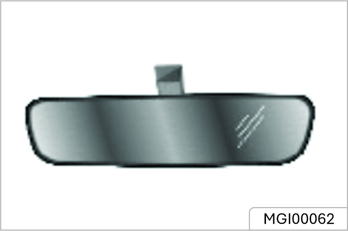
When the START/STOP switch is in position ON/RUNNING, the automatic anti-dazzle function is switched on automatically. When a flowing vehicle's headlamps could dazzle the driver, the light sensor activates the antidazzle function. The automatic anti-dazzle function can be inhibited if:
Attaching film on the rear window may have influences on the usage of automatic anti-dazzle function.
Manual Anti-Dazzle Interior Rearview Mirror *
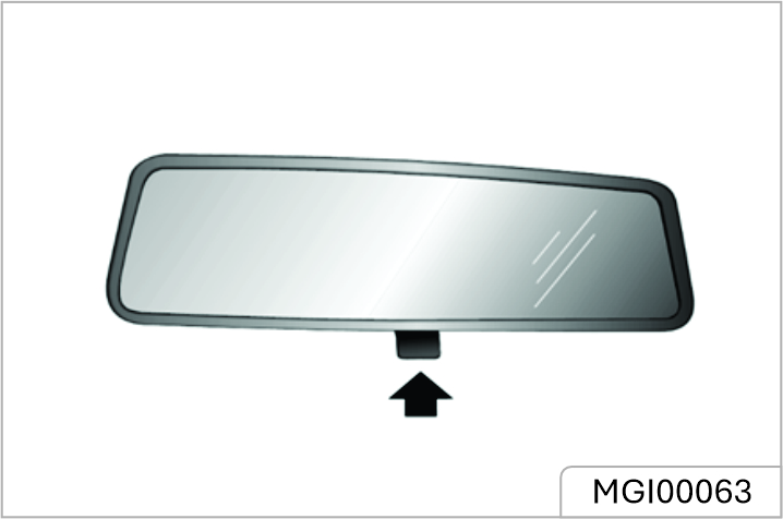
Move the lever at the base of the mirror forward to 'dip' the mirror and achieve the anti-dazzle function. Normal visibility is restored by pulling the lever back again.
In some circumstances, the view reflected in a 'dipped' manual mirror can confuse the driver as to the precise location of following vehicles.
The vanity mirror on the driver side should only be used when the
Sunvisors (1) are arranged on the roof ahead of both the driver and the front passenger. Some models have vanity mirror (2), depending on the vehicle configuration. For the models which have vanity mirror, pull the sunvisor downward and slide the cover aside to use the vanity mirror.
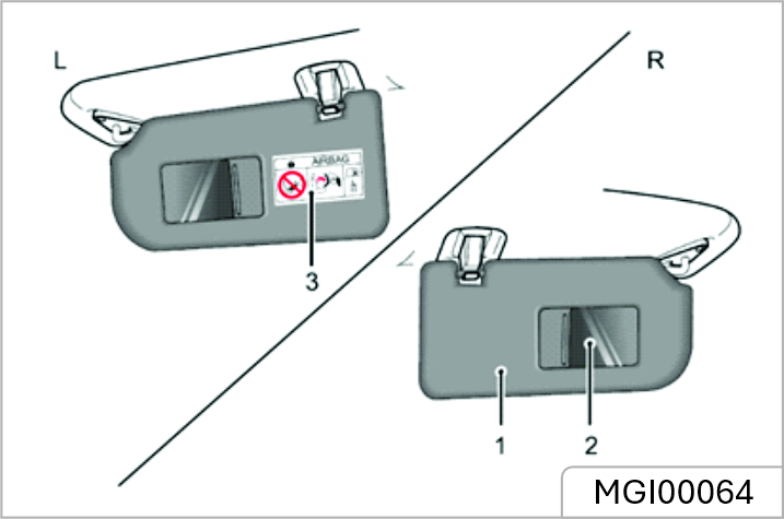
Warnings and instructions on use of child restraint (3) are attached to both sides of the passenger sunvisor. NEVER use a rearward facing child restraints on a seat protected by an ACTIVE AIRBAG in front of it, DEATH or SERIOUS INJURY to the CHILD can occur. Refer to 'Disabling the Passenger Airbag'.
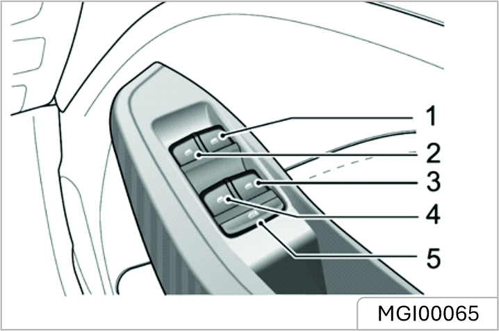
When the window is up or down, ensure the safety of the personnel in the vehicle, especially the children, to prevent being pinched by the window.
Push the switch (1-4) down to lower, and pull the switch up to raise the window. The window will stop moving as soon as the switch is released (unless the 'One-Touch' function is active).
The front and rear passenger windows can also be operated by individual window switches, mounted on each door. The rear window switches will not be operated if the rear window isolation switch has been activated. Electric window can be operated with the vehicle power system in the ACC, ON and RUNNING positions. (For safety: doors should be closed).
Rear Window Isolation Switch
Press the button (5) to isolate the rear window controls, press again to restore control.
It is recommended that you ISOLATE the rear window switches when carrying a child. Please operate the windows correctly to avoid danger, the driver shall instruct the occupants on the use of windows and safety precautions.
"One-Touch” Down
The driver's window control switch (1) has 2 positions. Short press the window control switch to the “2” position and release. The window automatically descends to fully open. Window movement can be stopped at desired position at any time by briefly operating the switch again
“One Touch” Up with “Anti-Trap”
The driver's window control switch (1) has the “one-touch” up function. Lifting the switch to the “2” position for a short time and releasing will automatically close the window completely. Window movement can be stopped at a desired position at any time by briefly operating the switch again. The “Anti-Trap” function is a safety feature which prevents the window from fully closing if an obstruction is sensed if this happens the window will open slightly to allow the obstruction to be removed.
DO NOT operate the power window controls continuously several times in a short time frame, otherwise the power window controls may be disabled to protect the motor. If this occurs, please wait a few seconds until the motor cools down. Do not disconnect the negative battery cable while waiting for the motor to cool down.
If the battery is cut off during lifting and lowering of the window, One Touch and Anti-Trap mode may be not operational. In this case, fully open the window, then raise the window to the fully closed position by lifting the switch briefly and consecutively. When the window is fully closed, hold the switch in the close position for a further 5 seconds. Then fully open the window again, press the switch for another 5 seconds, One Touch and Anti-Trap mode will be resumed.
The sunroof consists of two glass panels, only the front section can be opened by sliding or tilting. The sunshade can be opened or closed as a complete unit.
DO NOT allow passengers to lean out of an open sunroof whilst the vehicle is in motion. Injuries may occur from objects such as tree branches.
Safety of the vehicle occupants must be observed at all times. DO NOT allow limbs to be placed in the moving path of the sunroof at any time, injury may occur.
The sunroof will operate when the START/STOP Switch is set to ACC or ON/RUNNING.
Sunroof Glass Operation
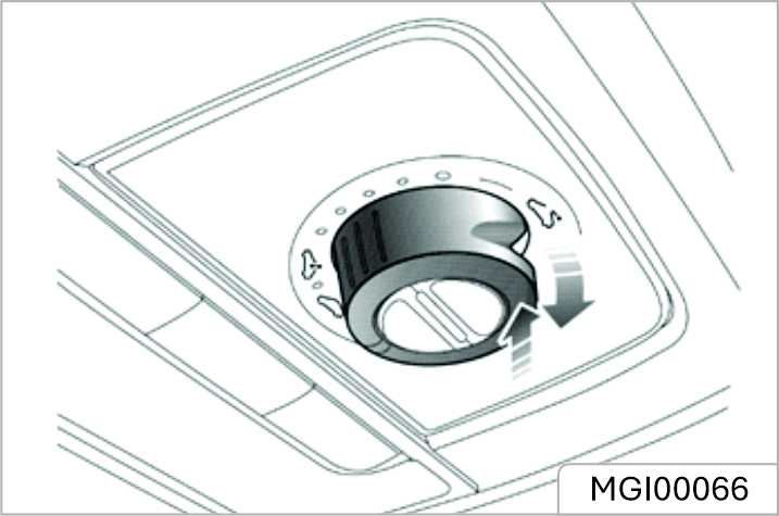
Opening the Sunroof Glass using Tilt
With the sunroof glass fully closed, press the rear part of the switch in the direction of the arrow as indicated in the graphic to fully 'tilt' the glass to the open position. Operation can be interrupted at the desired point by pressing the switch again
Closing the Sunroof Glass from Tilt
Pull down the rear of the switch to automatically close the sunroof in the direction as indicated by the arrow. Briefly pull down on the switch again will interrupt the operation at the desired position. To manually close the sunroof, pull down the rear of the switch in the direction as indicated by the arrow and hold, until the sunroof reaches the desired position.
Opening the Sunroof Glass by Sliding
![]() Rotate the switch completely
clockwise and hold until the sunroof
slides fully open. To partially open
the sunroof, place the switch in the
required range position.
Rotate the switch completely
clockwise and hold until the sunroof
slides fully open. To partially open
the sunroof, place the switch in the
required range position.
Closing the Sunroof Glass by Sliding
![]() Rotate the switch completely
counterclockwise, the sunroof will
slide fully closed. To partially close
the sunroof, place the switch in the
required range position.
Rotate the switch completely
counterclockwise, the sunroof will
slide fully closed. To partially close
the sunroof, place the switch in the
required range position.
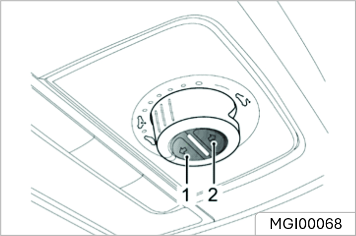
Opening The Sunshade
Short press the button (2) to automatically open the sunshade to its full extent. Short press the button at any time to cancel the request and stop the sunshade at that position. To manually open the sunshade, press and hold the button until the sunshade reaches the desired position, then release it
Closing the Sunshade
Short press the button (1) to automatically close the sunshade completely. Short press the button at any time to cancel the request and stop the sunshade at that position. To manually close the sunshade, press and hold the button until the sunshade reaches the desired position, and release it.
If the vehicle is to be parked in direct sunlight for a length of time it is recommended that the sunshade be closed to protect the interior trim components from damage, and to help regulate the in car temperatures.
The sunroof and sunshade feature an “Anti-Pinch” function, this is a safety feature which prevents the sunroof or sunshade from fully closing whilst in the automatic mode if an obstruction is sensed - if this happens the sunroof/sunshade will open slightly to allow the obstruction to be removed.
Forcibly Closing the Sunroof (over-riding the anti-pinch)
To forcibly close the sunroof glass after an anti-pinch intervention, gently slide the glass switch forwards to the 1st position and hold in position until the sunroof glass is fully closed.
The anti-pinch function is suspended during this operation.
Forcibly Closing the Sunshade (over-riding the anti pinch)
To forcibly close the sunshade that has reopened due to activation of anti-pinch function: gently slide the sunshade switch forwards to the 1st position and hold it until the sunshade closes fully.
The anti-pinch function is suspended during this operation.
In the event of a power failure or battery disconnection when the sunroof glass or sunshade is in motion, the sunroof/sunshade will require initialisation when the power is restored.
To carry out the sunroof glass initialisation operation:
Fully close the glass - gently pull the rear of the switch downward and hold in position for 10 seconds, the sunroof will open a preset amount and stop, it will then close automatically- the sunroof glass is then initialised. During the whole process, the switch must remain in the pulled down position.
To carry out the sunshade initialisation operation:
Fully close the sunshade - press the close switch and hold in position for 10 seconds, the sunshade will open a preset amount and stop, it will then close automatically- the sunshade is then initialised. During the whole process, the switch must remain pressed.
Thermal Protection
To prevent the sunroof glass motor and the sunshade motor from being overheated and damaged, the motors are designed with a thermal protection function.
after the thermal protection is active, the sunroof can only be closed, and will not respond to other operations. After the motor has cooled down and exits the
thermal protection state, the sunroof can be operated until the next thermal protection event.
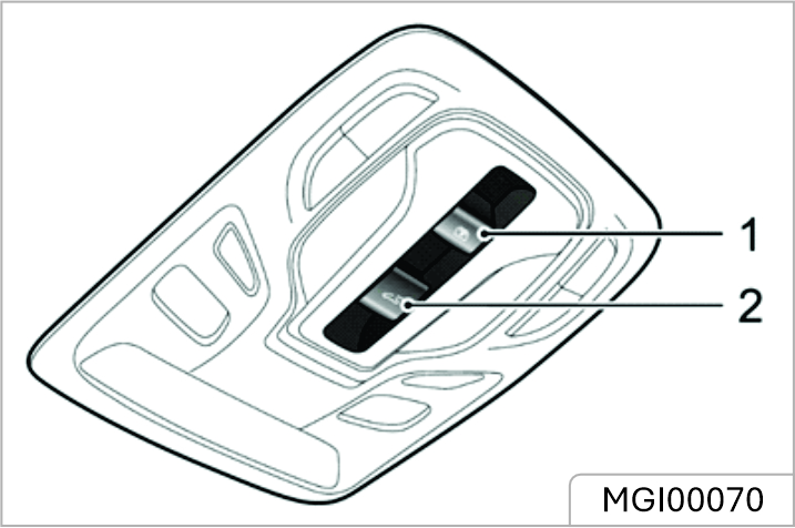
The sunroof will operate when the START/STOP Switch is set to ACC or ON/RUNNING. Switch 1 is used to operate the sunroof sunshade, and switch 2 is used to operate the sunroof glass. The method by which the sunroof will open function is identified by the icons on the switches.
Sunroof Glass Operation Open the Sunroof Glass by Tilting
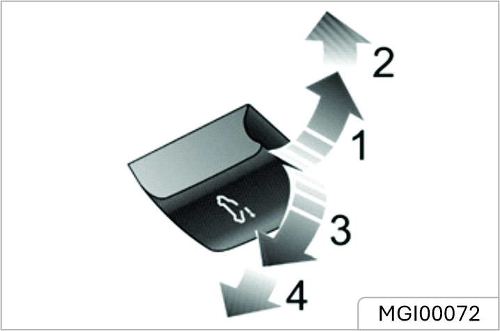
Push the sunroof glass switch upward to the 1st position (1) and hold, the sunroof will tilt open manually. You can stop the movement of the sunroof at any time by releasing the switch. Push the glass switch with slightly harder force to move the switch to its 2nd position (2) and then release, the sunroof will automatically open completely.
Close the Sunroof Glass by Tilting
Pull the sunroof glass switch downward to the 1st position (3) and hold, the sunroof will close manually. You can stop the movement of the sunroof at any time by releasing the switch. Pull the glass switch with slightly harder force to move the switch to
its 2nd position (4) and then release, the sunroof will automatically close completely.
Open the Sunroof Glass by Sliding
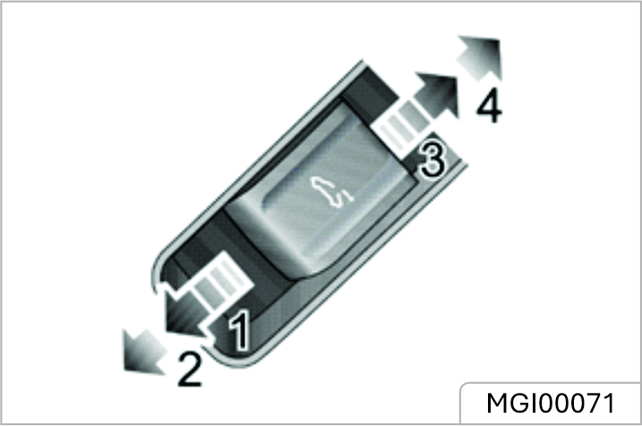
Push the sunroof glass switch backward to the 1st position (3) and hold, the sunroof will slide open manually. You can stop the movement of the sunroof at any time by releasing the switch. Push the glass switch backward with slightly harder force to move the switch to its 2nd position (4) and then release, the sunroof will automatically open fully. You can stop the movement of the sunroof at any time by pushing the switch backward again.
Close the Sunroof Glass by Sliding
Push the sunroof glass switch forward to the 1st position (1) and hold, the sunroof will close manually. You can stop the movement of the sunroof at any time by releasing the switch. Push the glass switch forward with slightly harder force to move the switch to its 2nd position (2) and then release, the sunroof will automatically fully close. You can stop the movement of the sunroof at any time by pushing the switch forward again.
Due to the design of the sunroof there may be occasions where using the manual close function provides a visual impression that the glass is fully closed, this may not be the case, it is recommended to use the 2nd position to automatically close the sunroof glass when it needs to be completely closed.
Open the Sunshade
Push the sunroof sunshade switch backward to the 1st position (3) and hold, the sunshade will slide open manually. You can stop the movement of the sunshade at any time by releasing the switch. Push the sunshade switch backward with slightly harder force to move the switch to its 2nd position (4) and then release, the sunshade will automatically open fully. You can stop the movement of the sunshade at any time by pushing the switch backward again.
Close the Sunshade
Push the sunroof sunshade switch forward to the 1st position (1) and hold, the sunshade will close manually. You can stop the movement of the sunshade at any time by releasing the switch.
Push the sunshade switch forward with slightly harder force to move the switch to its 2nd position (2) and then release, the sunshade will automatically fully close. You can stop the movement of the sunshade at any time by pushing the switch forward again.
If the vehicle is to be parked in direct sunlight for a length of time it is recommended that the sunshade be closed to protect the interior trim components from damage, and to help regulate in the car temperatures.
Anti-pinch Function
The sunroof and sunshade feature an “Anti-Pinch” function, this is a safety feature which prevents the sunroof or sunshade from fully closing whilst in the automatic mode if an obstruction is sensed - if this happens the sunroof/sunshade will open slightly to allow the obstruction to be removed.
Forcibly Closing the Sunroof (over-riding the anti-pinch)
To forcibly close the sunroof glass after an anti-pinch intervention, gently slide the glass switch forwards to the 1st position and hold in position until the sunroof glass is fully closed.
The anti-pinch function is suspended during this operation.
Forcibly Closing the Sunshade (over-riding the anti pinch)
To forcibly close the sunshade that has reopened due to activation of anti-pinch function: gently slide the sunshade switch forwards to the 1st position and hold it until the sunshade closes fully.
The anti-pinch function is suspended during this operation.
Linkage between Sunshade and Sunroof Glass
To prevent the sunshade from being exposed, the sunshade will move together with the sunroof glass as one unit when the sunroof is opened. To close the sunshade, please close the sunroof glass first.
In the event of a power failure or battery disconnection when the sunroof glass or sunshade is in motion, the sunroof/sunshade will require initialisation when the power is restored.
To carry out the sunroof glass initialisation operation:
Fully close the glass-gently slide the switch forward to the 2nd position and hold in position for 10 seconds. The sunroof will open a preset amount and stop, it will then close automatically - the sunroof glass is then initialised. During the whole process, the switch must remain in the 2nd position
To carry out the sunshade initialisation operation:
Fully close the sunshade -slide the close switch forward to the 2nd position and hold in position for 10 seconds. The sunshade will open a preset amount and stop, it will then close automatically - the sunshade is then initialised. During the whole process, the switch must remain in the 2nd position.
Thermal Protection
To prevent the sunroof glass motor and the sunshade motor from being overheated and damaged, the motors are designed with a thermal protection function. After the thermal protection is active, the sunroof can only be closed, and will not respond to other operations. After the motor has cooled down and exits the thermal protection state, the sunroof can be operated until the next thermal protection event.
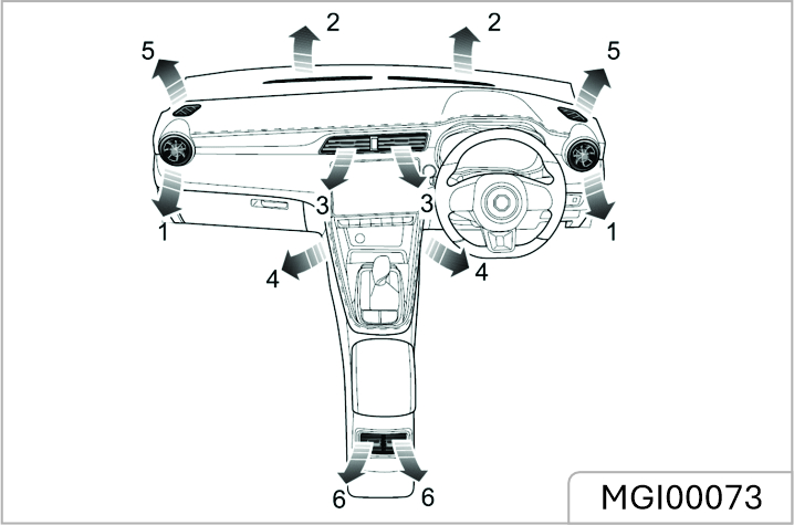
The air conditioning system is used to adjust the temperature, speed, humidity and cleanliness of the air in the car. Fresh air is drawn in through the air intake grille at the base of the front windscreen and A/C filter. Always keep the air intake grille clear of obstructions such as leaves, snow or ice.
A/C Filter
The A/C filter is used to filter air. To remain fully effective, the filter should be replaced at the recommended service interval.
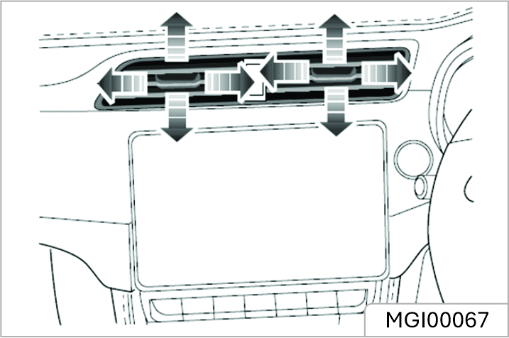
Slide the button in the centre of the louvres to the left or right to open or close the vent. Toggle the button at the centre of each vent up and down, left and right to regulate the air direction.
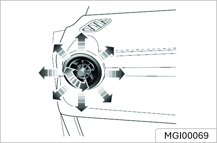
Rotate the centre thumb-wheel clockwise or anti-clockwise to open or close the vent. Toggle the centre thumb-wheel up, down, left or right to adjust the air direction.
Centre Console Vents
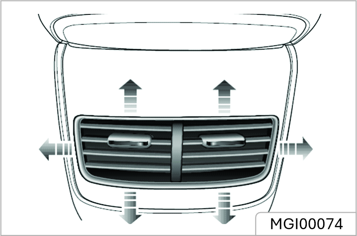
Slide the button in the centre of the louvres to the left or right to open or close the vent. Toggle the button at the centre of each vent up and down, left and right to regulate the air direction.
Control Panel
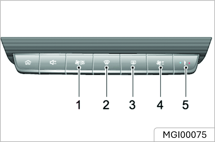
A/C Control Shortcut
Short press the A/C control
shortcut to display the air
conditioning interface on the
infotainment screen.
Long press the A/C control shortcut
to switch the system on, all
functions will revert to the state
before shutdown. Long press again
to switch off.
Defrost/Demist
Press Defrost/Demist Button on the control panel, the indicators on the button and display illuminate, the A/C cooling and external circulation functions are switched on, and the system enters the defrost/demist function to clear the windshield and side window. Press again to switch off. The indicator will go off and the system will return to the previous state.Whilst the defrost/demist is selected, operate the A/C on/off button to turn the compressor on/off; operate the air recirculation button to switch between internal recirculation and external circulation; operation of either of these functions will not affect the defrost/demist function;operation of any other air distribution modes will quit defrost/demist.
Heated Rear Window
The heating elements on the inside of the rear window are easily damaged. DO NOT scrape or scratch the inside of the glass. DO NOT stick labels over the heating elements.
Press the Heated Rear Window Button to switch the function on or off.The button indicator illuminates when the function is on, and is extinguished when the function is off.The heated rear window features a timer function and will automatically switch off after a present time. To continue to use the heated rear window, operate the button again.
Blower Speed Control Button
Press the blower speed control button upward or downward to regulate the blower speed.
Temperature Control Button
![]() Press the temperature control
button upward or downward to
regulate the temperature of the air
supplied by the vents.
Press the temperature control
button upward or downward to
regulate the temperature of the air
supplied by the vents.
Control Interface
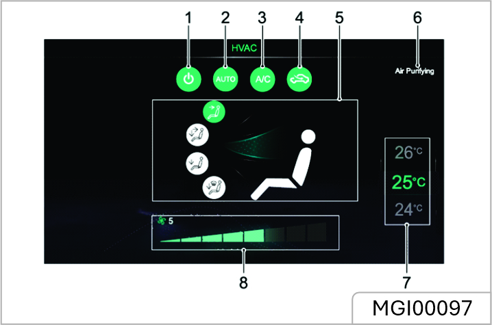
Control Interface - MY25
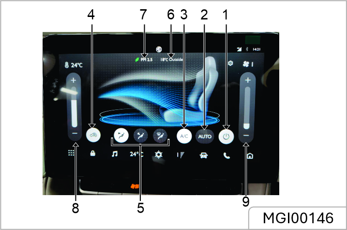
System On/Off
Touch the system On/Off Touch button to switch the system on or off.
Auto Mode
Set the target temperature required and then press the AUTO touch button to enable the auto mode function. In auto mode, the air distribution mode, blower speed and so on are automatically adjusted to reach and maintain the required temperature. The blower speed control will by default indicate full speed in auto mode. Manually adjust the air distribution mode or blower speed to exit auto mode. In this case the AUTO indicator will extinguish.
To ensure the auto mode operates efficiently, all windows and the sunroof must be closed and the air inlet grille must be clear of obstructions. In addition, the A/C Auto control sensor should not be covered.
Cooling On/Off
Touch the cooling On/Off touch button to operate the cooling function
A small amount of water may remain in the air conditioner after usage, this may produce a peculiar smell. If this is a particular issue, it is recommended to switch off the cooling function and run the blower for a while.
Air Circulation Mode
Touch the air recirculation mode touch button to switch between air recirculation modes.
![]() During internal recirculation,
the air conditioning system
circulates the air inside the car to
meet the requirements of rapid
cooling or heating, and at the same
time, it can prevent the entry of
traffic fumes.
During internal recirculation,
the air conditioning system
circulates the air inside the car to
meet the requirements of rapid
cooling or heating, and at the same
time, it can prevent the entry of
traffic fumes.
![]() During the external
circulation, the air conditioning
system draws air from outside the
vehicle to ensure fresh air enters the vehicle.
During the external
circulation, the air conditioning
system draws air from outside the
vehicle to ensure fresh air enters the vehicle.
![]() During automatic circulation,
the air conditioning system can
automatically adjust the internal
recirculation or external circulation
according to the situation.
During automatic circulation,
the air conditioning system can
automatically adjust the internal
recirculation or external circulation
according to the situation.
Leaving the system in internal recirculation mode can cause the windscreen to mist. If this happens, turn on the defrost/demist mode
Air Distribution Mode
Select the corresponding Air Distribution Mode Touch Button as required to regulate the air distribution mode.
To 'face'. Directs air to the centre, centre console and side vents.
To 'face' + 'feet'. Directs air to the centre, centre console, side and footwell vents.
To 'feet'. Directs air to the footwell vents.
In this mode, a small amount of airflow will be directed to the side, front side window and windscreen/defrost Vents.
Temperature Control
Touch the temperature control touch button to regulate the temperature of the air supplied by the vents.
Blower Speed Control
Touch the blower speed control touch button to regulate the blower speed.
Control Interface
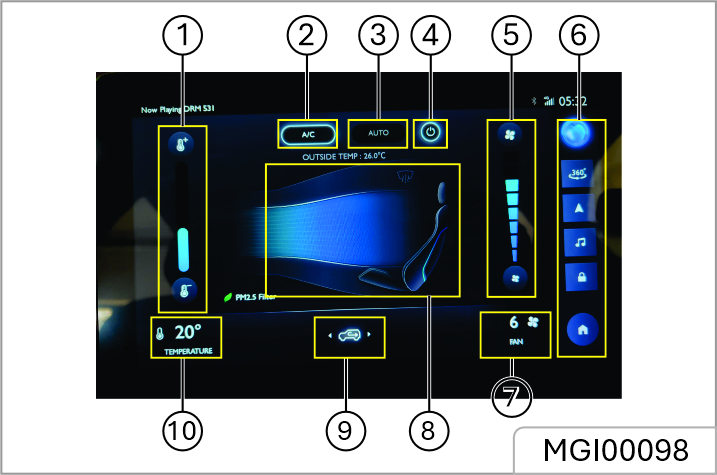
Temperature Control
Touch the temperature control touch button to regulate the temperature of the air supplied by the vents.
Cooling On/Off
Touch the cooling On/Off touch button to operate the cooling function.
A small amount of water may remain in the air conditioner after usage, this may produce a peculiar smell. If this is a particular issue, it is recommended to switch off the cooling function and run the blower for a while.
Auto Mode
Set the target temperature required and then press the AUTO touch button to enable the auto mode function. In auto mode, the air distribution mode, blower speed and so on are automatically adjusted to reach and maintain the required temperature. The blower speed control will by default indicate full speed in auto mode.Manually adjust the air distribution mode or blower speed to exit auto mode. In this case the AUTO indicator will extinguish.
To ensure the auto mode operates efficiently, all windows and the sunroof must be closed and the air inlet grille must be clear of obstructions. In addition, the A/C Auto control sensor should not be covered.
System On/Off
Touch the system On/Off touch button to switch the system on or off.
Blower Speed Control
Touch the blower speed control touch button to regulate the blower speed.
Air Distribution Mode
Select the corresponding Air Distribution Mode Touch Button as required to regulate the air distribution mode.
To 'Face'. Directs airflow to the side and centre vents.
To 'Face + Feet'. Directs air to footwell, side and centre vents.
To 'Feet'. Directs air to footwell vents.
In this mode, a small amount of airflow will be directed to the side, front side window and front windscreen vents.
To 'Feet + Windscreen'. Directs air to the footwell, front windscreen and front side window vents.
In this mode, a small amount of airflow will be directed to the side vents.
To 'windscreen'. Directs air to the windscreen/defrost and front side window vents.
In this mode, a small amount of airflow will be directed to the side vents.
Air Circulation Mode
Touch the air recirculation mode touch button to switch between air recirculation modes.
![]() During internal
recirculation, the air conditioning
system circulates the air inside the
car to meet the requirements of
rapid cooling or heating, and at the
same time, it can prevent the entry
of traffic fumes.
During internal
recirculation, the air conditioning
system circulates the air inside the
car to meet the requirements of
rapid cooling or heating, and at the
same time, it can prevent the entry
of traffic fumes.
![]() During the external
circulation, the air conditioning
system draws air from outside the
vehicle to ensure fresh air enters the
vehicle.
During the external
circulation, the air conditioning
system draws air from outside the
vehicle to ensure fresh air enters the
vehicle.
![]() During automatic
circulation, the air conditioning
system can automatically adjust
the internal recirculation or external
circulation according to the
situation.
During automatic
circulation, the air conditioning
system can automatically adjust
the internal recirculation or external
circulation according to the
situation.
Leaving the system in internal recirculation mode can cause the windscreen to mist. If this happens, turn on the defrost/demist mode.
Important Safety Information
Additional Notes
Basic Operations
Control Panel
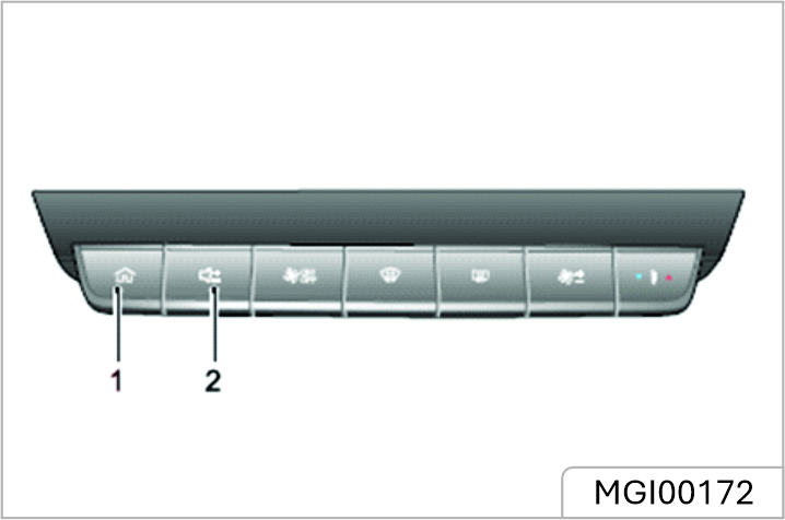
Main System Interface
For details about functional description of the Entertainment & Navigation system, please refer to the vehicle system Infotainment manual available in the Head Unit User Manual Section.
![]() If the HU is not activated and is not
having network connection, a QR
code will be displayed,
user can scan it and
download on the mobile
browser.
If the HU is not activated and is not
having network connection, a QR
code will be displayed,
user can scan it and
download on the mobile
browser.
If HU is activated and have network connected, the User manual QR Code will be downloaded & displayed in the English readable format on the same screen of HU.
displayed in the English readable format on the same screen of HU. Please note that whenever there will be POP up on Infotainment system for Software/FOTA update, please update the HU software for new features and system performance enhancement.
At the same time, always ensure your handheld device (Android & IOS) must be on latest version. To get the latest version, check the software update in Phone settings.
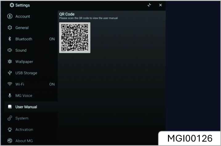
Power On/Off
Power On
If the vehicle power is turned off with the system currently in playback mode, the system will be automatically powered on when the vehicle power is turned on again. If the vehicle power is turned off with the system in the standby state, short press the Power button on the system control panel to power-on the system after the vehicle power is turned on again. With the system on, long press the HOME button on the system control panel to enter the Standby mode; keep pressing the button and the system will reboot automatically.
Power Off
Pressing the START/STOP Switch to the Off position will automatically switch off the infotainment system.
Standby Mode
With the START/STOP Switch on, long press the HOME button to allow the Infotainment system to enter the Standby mode, the operation of the Infotainment system may be suspended. In standby mode, all sounds will be muted. To cancel the Standby mode,short press the HOME button.
The following operations can also cancel the Standby mode:
Control Buttons on Steering Wheel
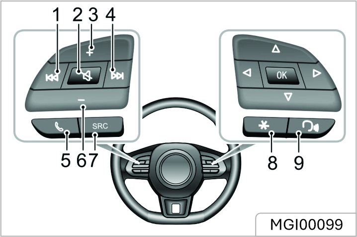
Volume Adjustment
The audio volume can be adjusted by the control panel and the buttons on the steering wheel. During the volume adjustment, the system automatically pops up a volume indication window which changes smoothly with the adjustment process.
The volume buttons on the steering wheel and control panel can only be used for the volume adjustment of audios of media and communication type.
The playback volume of Bluetooth music can be adjusted by the device itself and the Infotainment player
Connecting/Disconnecting a USB
Storage Device
Inserting a USB Storage Device
Connect a USB device to the USB port for connection.
Removing a USB Storage Device
Check and confirm that there is no data being accessed, then pull out the USB storage device.
If data loss or damage to the storage device occurs for any reason, the data will generally never be recovered. For damages, costs or expenses due to data loss or damage, the manufacturer assumes no responsibility.
Some USB storage devices may be unidentifiable.
The Infotainment system may not achieve its optimum performance when using with some USB storage devices.
Using USB hub or extension cable may not identify USB device.
Bluetooth Phone
Instructions
Bluetooth Pairing and Connection
If Bluetooth is not enabled, no Bluetooth icon is displayed in the status bar; if Bluetooth is enabled but no device is connected, is displayed in the status bar; if Bluetooth is enabled and any device is connected, is displayed in the status bar.
The steps of Bluetooth pairing and connection are as follows:
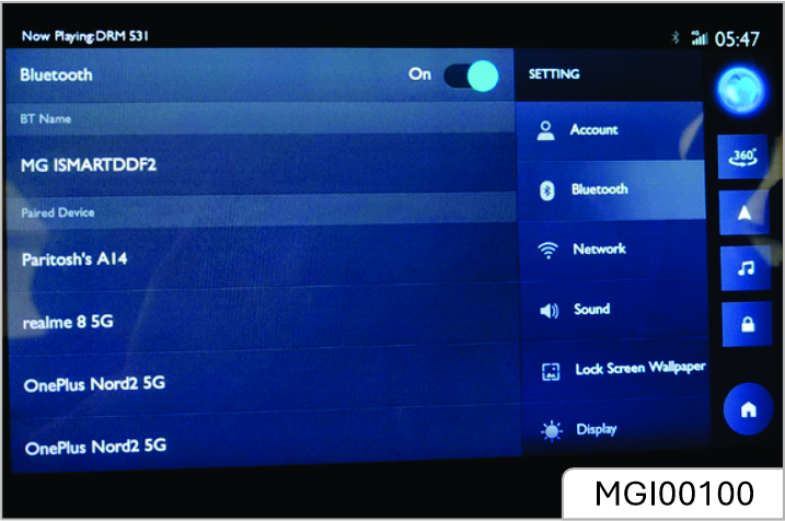
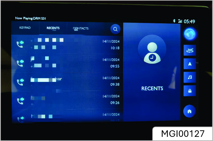
You may make a call using the following methods:
You may end a call using the following methods:
Incoming Call
Answer an Incoming Call
Reject an Incoming Call
Switch to Private Mode
In Private Mode, you may continue with the call using the mobile phone; the speakers and microphone of the Infotainment system will be muted. But Bluetooth is still connected.
Entertainment
Precautions for Playing a Storage
Medium
Mode
Radio
Touch the Radio/Music area in the main interface, and touch [Radio] again to enter the Radio interface. To listen to the broadcasting of different radio bands.
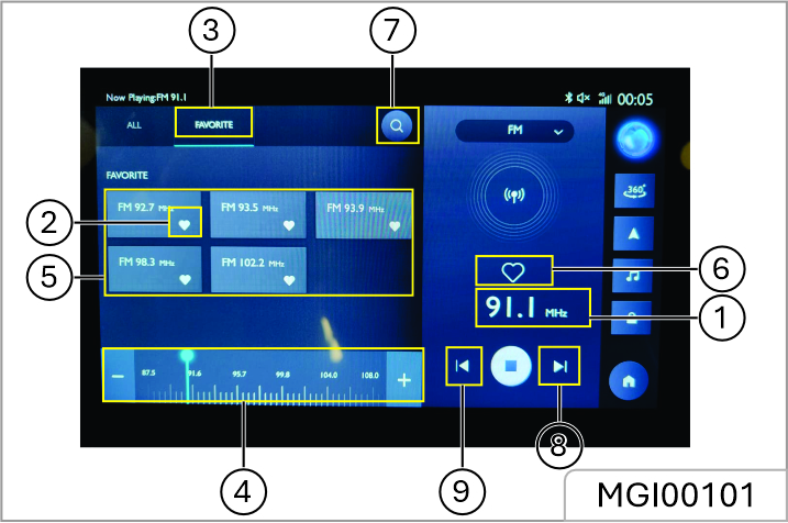
Automatically search for and preview each station and play each for 10 s. During the preview, click the button to terminate the preview function, and play the current previewing station
Short press to automatically search for the next station; long press to manually search for the next station.
Short press to automatically search for the previous station; long press to manually search for the previous station.
Touch [Audio] in this interface, and the system skips to the Audio Settings interface.
USB Music
Insert a USB storage device into the USB port, and the system automatically loads the music from the storage device. Touch the Radio/Music area in the main interface, and touch [USB Music] again to enter the USB Music Playback interface.
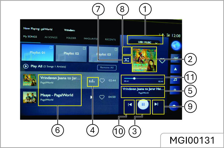
When there are two USB drives, you may choose to play music in USB1 or USB2
Track playback progress is displayed by the coil, drag the progress bar to skip to certain playing point.
Touch to enter the corresponding Folder List interface, then touch to select and play the track you prefer.
You may switch between Random Playback and Folder Random Playback.
You may switch between Single Loop, Folder Loop and Loop All.
Short press to switch to the next track; long press to fast forward.
Short press to switch to the previous track; short press during playing to return to the beginning of the track; long press to fast rewind.
Touch [Audio] in this interface, and the system skips to the Audio Settings interface.
Bluetooth Music
Please connect a Bluetooth device first before playing Bluetooth music. Refer to “Bluetooth Pairing and Connection” in “Bluetooth Phone” section for details. After the Bluetooth device is connected with the system, touch the Radio/Music area in the main interface, and then touch [BT Music] to enter the Bluetooth Music playback interface.
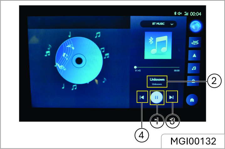
USB Video
Insert a USB storage device into the USB port, and the system automatically loads the videos from the storage device.
Due to differences in the compression ratio and bit rate of the multimedia formats downloaded from the Internet and other factors, the actual situation of the decoding result shall prevail.
For your driving safety, when the vehicle speed reaches a certain value, the video safety mode will be activated automatically, the video cannot be played at that moment
The video cannot be played during a call.
Touch [Video] in the main interface to enter the Video Playback interface
When playing a video, touch the screen to wake up the menu bar mode, and touch it again to exit the menu bar mode
1. Current Elapsed Time
2. Previous Video Short press to switch to the previous video; long press to fast rewind.
3. Playback Progress Bar Drag the progress bar to skip to certain playing point.
4. Play/Pause
5. Next Video Short press to switch to the next video; long press to fast forward.
6. Video List You may view and play the corresponding video file
7. Total Video Duration
8. USB Drive When there are two USB drives, you may choose to play videos in USB1 or USB2.
Pictures
Insert a USB storage device into the USB port, and the system automatically loads the pictures in the storage device. Touch [Pictures] in the main interface to enter the picture Playback interface.
Touch a picture file to display it in full screen.
Whilst viewing a picture file, touch the screen to wake up the menu bar mode, and touch it again to exit the menu bar mode.
Picture Browsing Interface
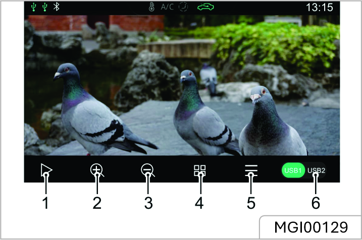
1. Slide Show
2. Zoom In
3. Zoom Out
4. Thumbnail
5. Pictures List You may view and play the corresponding picture file
6. USB Drive When there are two USB drives, you may choose to view pictures in USB1 or USB2.
The system supports the viewing of pictures stored on a USB device. Due to di
Swipe to the left or right on the screen to switch to the next or previous picture
Vehicle-Mobile Phone
Interconnection *
Only applicable to models that feature Vehicle-Mobile Phone Interconnection. Only the USB interface with can support vehicle mobile phone interconnection.
Apple CarPlay *
Apple CarPlay enables information interaction between the mobile phone and the on-board Infotainment system, including map, music, telephone, short message, podcast, voice recognition.
Connection Method
1. Confirm that your mobile phone has the CarPlay function and that it is turned on.
2. Connect the mobile phone to the Infotainment system mainframe using a suitable USB cable.
3. In the main interface, touch [Apple CarPlay] * area to enter the Apple CarPlay interface.
4. After the vehicle and mobile phone are successfully connected, you can operate the iPhone using the Infotainment system screen.
5. Press the HOME button on the control panel to return to the main system interface.
Android Auto *
Android Auto enables information interaction between the android mobile phone and the on-board Infotainment system, including map, music, telephone, messages, voice commands.
For the initial application, download and install Android Auto APP to your mobile phone from the market in which it will be operating.
When using, connect the mobile phone to the Infotainment system mainframe using a suitable USB cable. In the main interface, touch [Android Auto] * area to enter the Android Auto interface. Operate according to the interface prompt, then you can use the function once the connection is successful.
A/C
Touch the A/C area in the main interface to enter the A/C System Settings interface. Refer to “A/C Control Interface - Non Navigation *” in this Manual for details
Vehicle Settings
Touch [Car] in the main interface to enter the Vehicle Settings interface. You can set up the lighting, HVAC, etc.
After restoring factory settings, the vehicle settings of mainframe is reset to its original settings. Please use with caution.
Settings
Touch [Setup] in the main interface to enter the Settings interface. You can view the system information and set up the Audio , Time & Date , etc.
In the system information interface, you can choose to restore the factory settings as required. After restoring factory settings, the mainframe is reset to its original settings and all data in the Infotainment system will be deleted. Please use with caution.
Main Interface
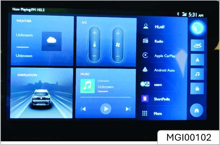
| No. | Describe |
|---|---|
| 1 | More Touch to see more interface |
More Interface
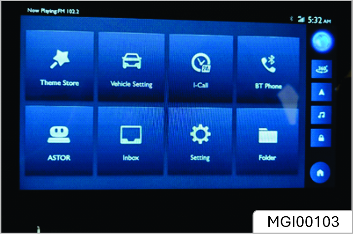
| No. | Describe |
|---|---|
| 1 | ASTOR Touch to enter ASTOR interface |
ASTOR Interface
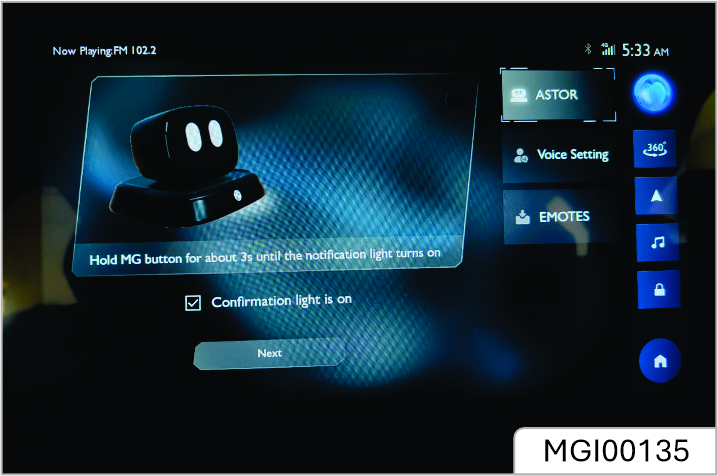
| S.No. | Description |
|---|---|
| 3 | Robot Screen Brightness - Swipe to adjust robot screen brightness. |
| 4 | Connection Info - View the robot connection information. |
| 5 | Connection Reset - Touch to reset robot connection. |
| 6 | Background APP Refresh - Automatically turn background app refresh on or off. |
| 7 | Version Info View the robot version. |
| 8 | Detect Touch to detect robot version. |
| 9 | Voice Setting Touch to enter the Voice Setting interface. |
Voice setting Interface

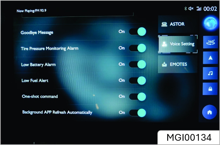
| S.No. | Description |
|---|---|
| 10 | Hello ASTOR - You can choose to turn the wake-up word on or off. |
| 11 | Welcome Message You can choose to hear the random or customized welcome message when you turn on the entertainment system. |
| 12 | Welcome Message mode You can choose to hear the random or customized welcome message when you turn on the entertainment system. |
| 13 | Goodbye Message You can choose to turn the goodbye message on/off |
| 14 | Tire Pressure Monitoring Alarm You can choose to turn the tire pressure monitoring alarm on/off |
| 15 | Low Battery Alarm You can choose to turn low battery alarm on/off |
| 16 | Low Fuel Alert You can choose to turn low fuel alert on/off |
| 17 | One-shot Command You can choose to turn one-shot command on/off |
| 18 | Background APP Refresh Automatically Turn background APP refresh automatically on or off |
| 19 | Version Info View the voice version information and touch to detect voice version. |
Robot is not connected and needs to be paired
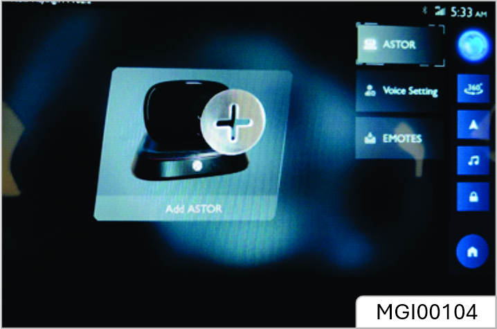
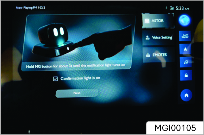
| S.No. | Description |
|---|---|
| 1 | Click the Add ASTOR button to start pairing robot. |
| 2 | As shown in the diagram, hold MG button for about 3s until the notification light turns on. |
| 3 | After the light turns on, check the confirmation box. |
| 4 | Click the next button to start pairing. |
| 5 | Pairing needs to wait for a while, and then it shows that the pairing is successful. |
Talking Robo Troubleshooting
Don'ts
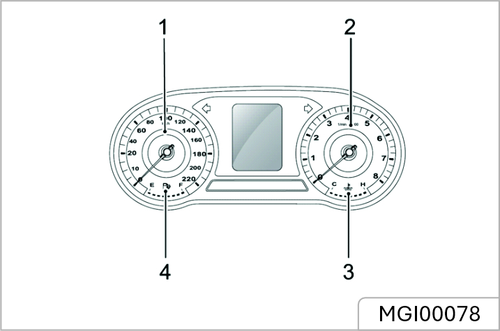
Instrument Pack - Colour Display A *
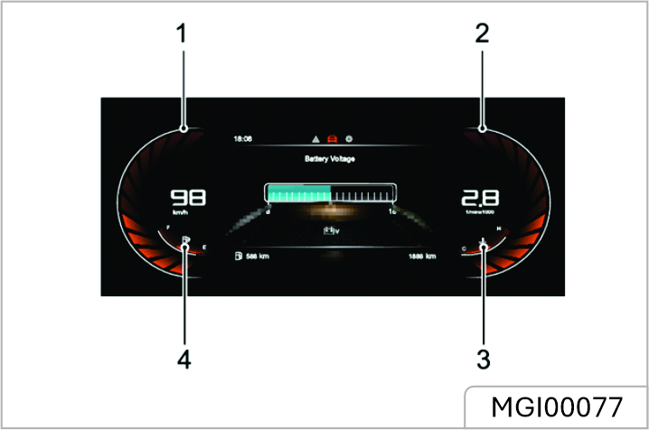
Speedometer (1)
Indicates the vehicle speed in km/h.
Tachometer (2)
Indicates the engine speed, ×1000 rpm.
Engine Coolant Temperature Gauge (3)
Indicates the engine coolant temperature.
Fuel Gauge (4)
Indicates the quantity of fuel in the tank. The low fuel warning lamp will illuminate yellow or flash when the fuel remaining in the fuel tank is low.
Indicates that the fuel filler is located on the right side of the vehicle.
Instrument Pack - Colour Display B*
Speedometer (1)
Indicates the vehicle speed in km/h.
Tachometer (2)
Indicates the engine speed, ×1000 rpm.
Engine Coolant Temperature Gauge (3)
Indicates the engine coolant temperature.
Fuel Gauge (4)
Indicates the quantity of fuel in the tank. The low fuel warning lamp will illuminate yellow or flash when the fuel remaining in the fuel tank is low.
Indicates that the fuel filler is located on the right side of the vehicle.
Information Centre - Colour Display A *
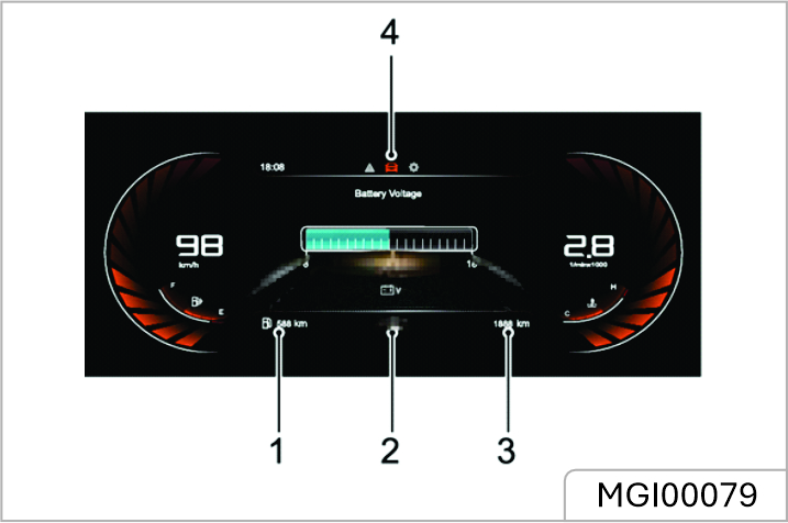
The information centre provides the followings:
1 Range To Empty
2 Gear Display *
3 Total Mileage
4 General Information
Range To Empty
Displays the estimated mileage that the vehicle can travel before the fuel gauge reads empty.
Gear Display *
Displays the current gear position of the transmission (P, R, N, D, S ,1,2 ,3 ,4 ,5 ,6 ,7 *,8 *). If “EP” is displayed, it indicates that a fault has been detected with the transmission. Please seek the JSW MG Authorised Service Center as soon as possible. Refer to “Starting & Driving” section.
Total Mileage
Displays the total driving mileage of the vehicle.
General Information
The general information function can be selected as follows:
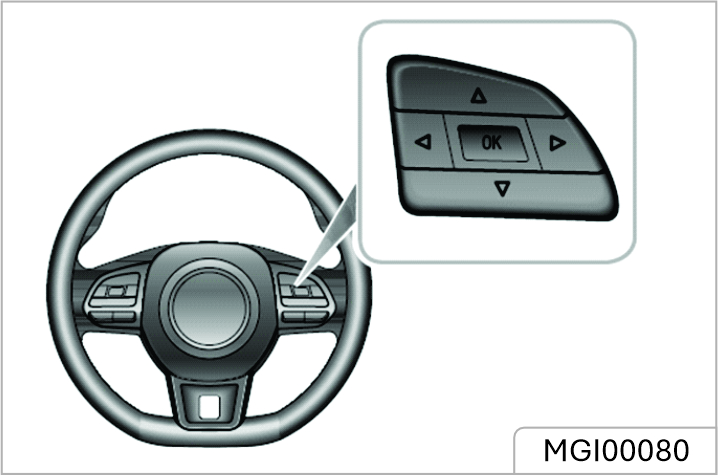
General information provides the following:
1. Warning Information
2. Trip Computer
3. Setting
4. Active Safety*
Warning Information
Displays the warning information or important notes that are currently relevant to the vehicle
Trip Computer
Trip computer functions contain the following:
Setting
Brightness
Displays the current level and allows adjustment of the backlight brightness.
Next Service
Displays and facilitates the reset of the current vehicle maintenance information.
Active Safety *
Displays the information of active safety
Warning Message
Warning messages and prompts are displayed in the information centre in the instrument pack. Any communications are displayed in 'pop up' messages, these can be divided into the following categories:
Please follow the instructions displayed in the 'pop up' message or in the case of a warning message, please refer to the relevant section of the owners manual to follow the correct instructions.
The following are a selection of warning messages that may appear in the information centre.
| Warning Message | Procedure |
|---|---|
| Cruise Control Fault | Indicates that the cruise control system has detected a fault. Please consult the JSW MG Authorised Service Center as soon as possible. |
| Active Speed Limiter Fault | Indicates that the active speed limit system has detected a fault. Contact the JSW MG Authorised Service Center as soon as possible. |
| Speed Assist System Fault | Indicates that the Speed Assist System (SAS) has failed. Please consult the JSW MG Authorised Service Center as soon as possible. |
| Engine Coolant Temperature High | High engine coolant temperature could result in severe damage. As soon as conditions permit, safely stop the vehicle and switch off the engine. |
| Warning Message | Procedure |
|---|---|
| Engine Coolant Temperature Sensor Fault | Indicates that the engine coolant temperature sensor has failed. As soon as conditions permit, safely stop the vehicle and switch off the engine and contact the JSW MG Authorised Service center immediately |
| Low Oil Pressure | Indicates that the oil pressure is too low, which may result in severe engine damage. As soon as safety permits, stop the car, switch off the engine and check the engine oil level.contact the JSW MG Authorised Service Center as soon as possible |
| Engine Fault | Indicates that a failure has occurred that will effect engine performance and emissions.Contact the JSW Authorised Service Center as soon as possible |
| Warning Message | Procedure |
|---|---|
| Check Engine | Indicates that a failure has occurred that many severely damage the engine. As soon as conditions permit safely stop the vehicle, switch off the engine and contact the JSW MG Authorised Service Center immediately |
| Clutch Switch Fault | ndicates that the clutch switch has detected a fault. Please consult the JSW MG Authorised Service Center as soon as possible. |
| Ignition System Fault | Indicates that the ignition system has detected a fault. Please consult the JSW MG Authorised Service Center immediately. |
| Start Stop Button Fault | Indicates that the Start Stop button has detected a fault. Please consult the JSW MG Authorised Service Center immediately. |
| Passive Entry Fault | ndicates that the passive keyless entry (PKE) function has detected a fault. Please consult the JSW MG Authorised Service Center as soon as possible. |
| Warning Message | Procedure |
|---|---|
| Engine Coolant Temperature Sensor Fault | Indicates that the engine coolant temperature sensor has failed. As soon as conditions permit, safely stop the vehicle and switch off the engine and contact the JSW MG Authorised Service center immediately |
| Low Oil Pressure | Indicates that the oil pressure is too low, which may result in severe engine damage. As soon as safety permits, stop the car, switch off the engine and check the engine oil level.contact the JSW MG Authorised Service Center as soon as possible |
| Engine Fault | Indicates that a failure has occurred that will effect engine performance and emissions.Contact the JSW Authorised Service Center as soon as possible |
| Warning Message | Procedure |
|---|---|
| Check Engine | Indicates that a failure has occurred that may severely damage the engine. As soon as conditions permit, safely stop the vehicle, switch off the engine and contact the JSW MG Authorised Service Center immediately |
| Clutch Switch Fault | Indicates that the clutch switch has detected a fault. Please consult the JSW MG Authorised Service Center as soon as possible. |
| Ignition System Fault | Indicates that the ignition system has detected a fault. Please consult the JSW MG Authorised Service Center immediately |
| Start Stop Button Fault | Indicates that the Start Stop button has detected a fault. Please consult the JSW MG Authorised Service Center immediately |
| Passive Entry Fault | Indicates that the passive keyless entry (PKE) function has detected a fault. Please consult the JSW MG Authorised Service Center as soon as possible. |
| Warning Message | Procedure |
|---|---|
| ABS Fault | Indicates that the anti-lock brake system (ABS) has failed and the ABS function is about to be disabled. Please consult the JSW MG Authorised Service Center immediately. |
| Brake Fault | Indicates that the brake fluid could be low or a fault has been detected in the Electronic Brake force Distribution (EBD) system. As soon as safety permits, stop the car, switch off ythe engine and check the brake fluid level.Contact the JSW MG AUthorised Service Center as soon as Possible. |
| Stability Control Fault | Indicates that the stability control system has detected a fault. Please consult the JSW MG Authorised Service Center immediately. |
| Traction Control Fault | Indicates that the traction control system has detected a fault. Please consult the JSW MG Authorised Service Center immediately. |
| Warning Message | Procedure |
|---|---|
| EPB System Fault | Indicates that the electronic parking brake system (EPB) has detected a fault. Please consult the JSW MG Authorised Service Center as soon as possible. |
| Park Brake Force Not Enough | Indicates that there is an issue with the electronic parking brake, it may not be able to provide adequate clamping force. Contact the JSW MG Authorised Service Center as soon as possible. |
| Autohold Fault | Indicates that the Autohold System has detected a fault. Please consult the JSW MG Authorised Service Center as soon as possible. |
| Hill Descent Control Fault | Indicates that the hill descent control system has detected a fault. Please consult the JSW MG Authorised Service Center as soon as possible. |
| Warning Message | Procedure |
|---|---|
| Steering Angle Uncalibrated | Indicates that the steering angle sensor is not calibrated. Please consult the JSW MG Authorised Service Center as soon as possible. |
| ESCL Fault | Indicates that a fault has been detected with the Electronic Steering Column Lock (ESCL). As soon as conditions permit, safely stop the vehicle and switch off the engine. Contact the JSW MG Authorised Service Center as soon as possible |
| Fuel Sensor Fault | Indicates that fuel sensor has detected a fault. Please consult the JSW MG Authorised Service Center as soon as possible. |
| Airbag Fault | Indicates that the Airbag system has detected a fault. As soon as conditions permit, safely stop the vehicle and switch off the engine and contact the JSW MG Authorised Service Center immediately |
| Warning Message | Procedure |
|---|---|
| Front Left/ Front Right/ Rear Left/ Rear Right Tyre Sensor Battery Low | Indicates that the Tyre Pressure Monitoring system has detected that a tyre pressure sensor has a low battery. Please consult the JSW MG Authorised Service Center as soon as possible. |
| TPMS Fault | Indicates that the tyre pressure monitoring system has detected a fault. Please consult the JSW MG Authorised Service Center as soon as possible. |
| 12V Battery Charging System Fault | Indicates that the IIndicates that the 12V battery charging system has failed. Please consult the JSW MG Authorised Service Center immediately |
| Front Camera System Fault | It indicates that the front camera has detected a fault. Please consult the JSW MG Authorised Service Center as soon as possible. |
| Front Camera Calibration Failed | Indicates that the front view camera module (FVCM) calibration has failed. Please consult the JSW MG Authorised Service Center as soon as possible. |
| Warning Message | Procedure |
|---|---|
| RADAR Calibration Failed | Indicates that the radar module calibration has failed. Please consult the JSW MG Authorised Service Center as soon as possible. |
| Lane Departure Warning System Fault | Indicates that the lane departure warning system (LDW) has detected a fault. Please consult the JSW MG Authorised Service Center as soon as possible. |
| Lane Keep Assist System Fault | Indicates that the lane keep assist system (LKA) has detected a fault. Please consult the JSW MG Authorised Service Center as soon as possible. |
| Forward Collision System Fault | Indicates that the forward collision warning system (FCW) has detected a fault. Please consult the JSW MG Authorised Service Center as soon as possible. |
| Auto Emergency Braking System Fault | Indicates that the auto emergency braking system (AEB) has detected a fault. Please consult the JSW MG Authorised Service Center as soon as possible |
| Warning Message | Procedure |
|---|---|
| Pedestrian Auto Emergency Braking Fault | Indicates that the auto emergency braking system for pedestrians (AEBP) has detected a fault. Please consult the JSW MG Authorised Service Center as soon as possible. |
| ACC System Fault | Indicates that the adaptive cruise control system (ACC) has detected a fault. Please consult the JSW MG Authorised Service Center as soon as possible. |
| Rear Drive Assist System Fault | Indicates that the Indicates that the rear drive assist system (RDA) has detected a fault. Please consult the JSW MG Authorised Service Center as soon as possible. |
Information Centre - Colour Display B *
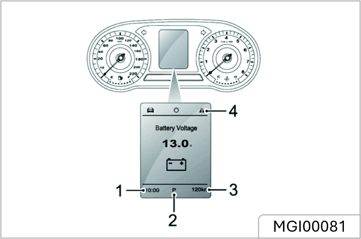
1. Digital Clock
2. Gear Display *
3. Total Mileage
4. General Information
Digital Clock
Displays the current time in digital form.
Gear Display *
Displays the current gear position of the transmission (P, R, N, D, S, 1, 2, 3, 4, 5, 6, 7*, 8*). If “EP” is displayed, it indicates that a fault has been detected with the transmission. Please seek the JSW MG Authorised Service Center as soon as possible. Refer to “Starting & Driving” section.
Total Mileage
Displays the total driving mileage of the vehicle.
General Information
The general information function can be selected as follows:
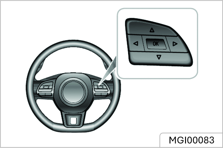
General information provides the following:
1. Trip Computer
2. Setting
3. Warning Information
Trip Computer
Trip computer functions contain the following:
Setting
Brightness
Displays the current level and allows adjustment of the backlight brightness.
This option can only be adjusted when the side lamps are on.
Next Service
Displays and facilitates the reset of the current vehicle maintenance information.
Warning Information
Displays the warning information or important notes that are currently relevant to the vehicle
Warning Message
Warning messages and prompts are displayed in the information centre in the instrument pack. Any communications are displayed in 'pop up' messages, these can be divided into the following categories:
Please follow the instructions displayed in the 'pop up' message or in the case of a warning message, please refer to the relevant section of the owners manual to follow the correct instructions.
The following are a selection of warning messages that may appear in the information centre.
| Warning Message | Procedure |
|---|---|
| Engine Coolant Temperature High | High engine coolant temperature could result in severe damage. As soon as conditions permit, safely stop the vehicle and switch o the engine and contact the JSW MG Authorised Service Center immediately |
| Engine Coolant Temperature Sensor Fault | Indicates that the engine coolant temperature sensor has failed. As soon as conditions permit, safely stop the vehicle and switch o the engine and contact the JSW MG Authorised Service Center immediately. |
| Low Oil Pressure | Indicates that the oil pressure is too low, which may result in severe engine damage. As soon as safety permits, stop the car, switch o the engine and check the engine oil level. Contact the JSW MG Authorised Service Center as soon as possible. |
| Warning Message | Procedure |
|---|---|
| Engine Fault | Indicates that a failure has occurred that will effect engine performance and emissions. Contact the JSW MG Authorised Service Center as soon as possible. |
| Check Engine | Indicates that a failure has occurred that may severely damage the engine. As soon as conditions permit, safely stop the vehicle , switch o the engine and contact the JSW MG Authorised Service Center immediately. |
| Clutch Switch Fault | Indicates that the clutch switch has detected a fault. Please consult the JSW MG Authorised Service Center as soon as possible. |
| Ignition System Fault | Indicates that the ignition system has detected a fault. Please consult the JSW MG Authorised Service Center immediately. |
| Warning Message | Procedure |
|---|---|
| Start Stop Button Fault | Indicates that the Start Stop button has detected a fault. Please consult the JSW MG Authorised Service Center immediately. |
| ABS Fault | Indicates that the antilock brake system (ABS) has failed and the ABS function is about to be disabled. Please consult the JSW MG Authorised Service Center immediately. |
| Brake Fault | Indicates that the brake fluid could be low or a fault has been detected in the Electronic Brakeforce Distribution (EBD) system. As soon as safety permits, stop the car, switch o the engine and check the brake fluid level. Contact the JSW MG Authorised Service Center as soon as possible. |
| Stability Control Fault | Indicates that the stability control system has detected a fault. Please consult the JSW MG Authorised Service Center immediately. |
| Warning Message | Procedure |
|---|---|
| Traction Control Fault | Indicates that the traction control system has detected a fault. Please consult the JSW MG Authorised Service Center immediately. |
| EPB System Fault | Indicates that the electronic parking brake system (EPB) has detected a fault. Please consult the JSW MG Authorised Service Center as soon as possible. |
| Park Brake Force Not Enough | Indicates that there is an issue with the electronic parking brake, it may not be able to provide adequate clamping force. Contact the JSW MG Authorised Service Center as soon as possible. |
| Autohold Fault | Indicates that the Autohold System has detected a fault. Please consult the JSW MG Authorised Service Center as soon as possible. |
| Warning Message | Procedure |
|---|---|
| Hill Descent Control Fault | Indicates that the hill descent control system has detected a fault. Please consult the JSW MG Authorised Service Center as soon as possible. |
| EPS Performance Reduced | Indicates that the electric power steering system has a general failure and that the steering performance has been reduced. As soon as conditions permit, safely stop the vehicle and switch off the engine. After a short while, start the engine, drive the vehicle a short distance and monitor the operation of the steering, if the message is still displayed or the steering assistance reduced please contact the JSW MG Authorised Service Center immediately. |
| Park Brake Force Not Enough | Indicates that there is an issue with the electronic parking brake, it may not be able to provide adequate clamping force. Contact the JSW MG Authorised Service Center as soon as possible. |
| EPS Assistance Failure | Indicates that the electric power steering system has failed. Please consult the JSW MG Authorised Service Center immediately. |
| Warning Message | Procedure |
|---|---|
| Steering Angle Fault | Indicates that the steering angle sensor has failed. Please consult the JSW MG Authorised Service Center as soon as possible. |
| Steering Angle Uncalibrated | Indicates that the steering angle sensor is not calibrated. Please consult the JSW MG Authorised Service Center as soon as possible. |
| Fuel Sensor Fault | Indicates that fuel sensor has detected a fault. Please consult the JSW MG Authorised Service Center as soon as possible. |
| Airbag Fault | Indicates that the Airbag system has detected a fault. As soon as conditions permit, safely stop the vehicle and switch o the engine and contact the JSW MG Authorised Service Center immediately. |
| Warning Message | Procedure |
|---|---|
| Airbag Lamp Fail | It indicates that the airbag lamp has failed. Please consult the JSW MG Authorised Service Center as soon as possible. |
| 12V Battery Charging System Fault | Indicates that the 12V battery charging system has failed. Please consult the JSW MG Authorised Service Center immediately |
Some warning lamps illuminate or flash accompanied by a warning tone.
High Beam Indicator - Blue
![]() The indicator illuminates
when the headlamp high beam is
turned on.
The indicator illuminates
when the headlamp high beam is
turned on.
Side Lamp Indicator - Green
![]() The indicator illuminates
when the side lamps are on.
The indicator illuminates
when the side lamps are on.
Auto Main Beam Indicator - Green
![]() The indicator illuminates
when the auto main beam function
has switched on the main beam
lamps
The indicator illuminates
when the auto main beam function
has switched on the main beam
lamps
Rear Fog Lamp Indicator - Yellow
![]() The indicator illuminates
when the rear fog lamps are on.
The indicator illuminates
when the rear fog lamps are on.
Front Fog Lamp Indicator - Green *
![]() The indicator illuminates
when the front fog lamps are on.
The indicator illuminates
when the front fog lamps are on.
Direction Indicator Lamp - Green
![]() The left and right direction
indicator lamps are represented by
directional arrows that are located
at the top of the instrument pack
The left and right direction
indicator lamps are represented by
directional arrows that are located
at the top of the instrument pack
When the turning signal lamp flashes, the direction indicator lamp on the corresponding side also flashes. If the hazard warning lamps are operated, both direction indicator lamps will flash together. If either direction indicator lamp in the instrument pack flashes very rapidly, it indicates that the turning signal light on the corresponding side has failed.
Failure of a side repeater lamp will have no eect on the flash frequency of direction indicator lamp.
Anti-theft System Warning Lamp - Red
![]() If no valid key is detected, this
lamp illuminates red. Please use the
correct key, or put the smart key at
the bottom of the centre console
cup holder. For specific location
requirements, refer to “Alternative
Starting Procedure” in “Starting &
Driving” section. If the remote key
battery is low, this lamp will flash.
Please replace the battery as soon
as possible.
If no valid key is detected, this
lamp illuminates red. Please use the
correct key, or put the smart key at
the bottom of the centre console
cup holder. For specific location
requirements, refer to “Alternative
Starting Procedure” in “Starting &
Driving” section. If the remote key
battery is low, this lamp will flash.
Please replace the battery as soon
as possible.
Airbag Warning Lamp - Red
![]() If this lamp illuminates, it
indicates that there is a failure in the
SRS or seat belt. Please seek the
JSW MG Authorised Service Center
at the earliest opportunity. An SRS
or seat belt fault may mean the
components may not be deployed
in the event of an accident.
If this lamp illuminates, it
indicates that there is a failure in the
SRS or seat belt. Please seek the
JSW MG Authorised Service Center
at the earliest opportunity. An SRS
or seat belt fault may mean the
components may not be deployed
in the event of an accident.
Seat Belt Unfastened Warning Lamp - Red
![]() If this lamp illuminates or
flashes, it indicates that the seat
belt for the driver or passenger
remains unfastened.
If this lamp illuminates or
flashes, it indicates that the seat
belt for the driver or passenger
remains unfastened.
Engine Malfunction Warning - Yellow
![]() This lamp will illuminate if an
engine fault occurs that will eect
engine performance during driving.
Please stop the car as soon as
safety permits, switch the engine
OFF and contact the JSW MG
Authorised Service Center
immediately
This lamp will illuminate if an
engine fault occurs that will eect
engine performance during driving.
Please stop the car as soon as
safety permits, switch the engine
OFF and contact the JSW MG
Authorised Service Center
immediately
Engine Emissions Malfunction Warning - Yellow
![]() If an engine fault occurs that
will eect engine performance and
emission after starting the vehicle,
this lamp will illuminate. Please
If an engine fault occurs that
will eect engine performance and
emission after starting the vehicle,
this lamp will illuminate. Please
contact the JSW MG Authorised Service Center as soon as possible.
Engine Coolant Temperature Warning - Red
![]() When the engine coolant
temperature warning lamp
illuminates red, it indicates that the
coolant temperature is high. High
engine coolant temperature could
result in severe damage. Please
stop the car as soon as safety
permits, switch the engine OFF and
contact the JSW MG Authorised
Service Center immediately
When the engine coolant
temperature warning lamp
illuminates red, it indicates that the
coolant temperature is high. High
engine coolant temperature could
result in severe damage. Please
stop the car as soon as safety
permits, switch the engine OFF and
contact the JSW MG Authorised
Service Center immediately
If this lamp flashes, it indicates that the coolant temperature sensor has a failure. Please stop the car as soon as safety permits, switch the engine OFF and contact the JSW MG Authorised Repairer immediately.
Low Oil Pressure Warning - Red
![]() If this lamp illuminates after
starting the vehicle, it indicates that
the oil pressure is too low, which
may result in severe engine damage.
Please stop the car as soon as
safety permits, switch the engine
OFF and check oil level (refer to
“Engine Oil Level Check and Top
Up” under the “Maintenance”).
Contact the JSW MG Authorised
Service Center immediately.
If this lamp illuminates after
starting the vehicle, it indicates that
the oil pressure is too low, which
may result in severe engine damage.
Please stop the car as soon as
safety permits, switch the engine
OFF and check oil level (refer to
“Engine Oil Level Check and Top
Up” under the “Maintenance”).
Contact the JSW MG Authorised
Service Center immediately.
Alternator Malfunction Warning - Red
![]() If this lamp illuminates after
starting the vehicle, it indicates that
the 12v battery charging system has
a failure. Please contact the JSW
MG Authorised Service Center
immediately. In cases of low battery
power, the prompt messages will
appear in the information centre. In
this case, the system will limit or
turn o some electrical devices,
please start the vehicle to charge
the battery
If this lamp illuminates after
starting the vehicle, it indicates that
the 12v battery charging system has
a failure. Please contact the JSW
MG Authorised Service Center
immediately. In cases of low battery
power, the prompt messages will
appear in the information centre. In
this case, the system will limit or
turn o some electrical devices,
please start the vehicle to charge
the battery
Cruise Control Indicator - Green/Yellow *
![]() If the cruise control function
is enabled, the system will enter
into the standby state and the
indicator illuminates in yellow.
If the cruise control function
is enabled, the system will enter
into the standby state and the
indicator illuminates in yellow.
When the cruise control system operates, this indicator illuminates green, indicating the cruise control system is activated.
If a failure in the cruise control system is detected, the indicator will flash in yellow. Please contact the JSW MG Authorised Service Center as soon as possible.
Tyre Pressure Monitoring System (TPMS) Warning Lamp - Yellow *
![]() If this lamp illuminates, it
indicates a tyre pressure is low,
please check the tyre pressures. If
this lamp flashes first and then
remains on after a period of time, it
indicates the system has a failure.
Please contact the JSW MG
Authorised Service Center at the
earliest opportunity
If this lamp illuminates, it
indicates a tyre pressure is low,
please check the tyre pressures. If
this lamp flashes first and then
remains on after a period of time, it
indicates the system has a failure.
Please contact the JSW MG
Authorised Service Center at the
earliest opportunity
Stability Control/Traction Control System Warning Lamp - Yellow *
![]() If this lamp illuminates, it
indicates that the stability
control/traction control system has
a failure. Please contact the JSW
MG Authorised Service Center
immediately. If this lamp flashes
during driving, it indicates the
system is operating to assist the
driver.
If this lamp illuminates, it
indicates that the stability
control/traction control system has
a failure. Please contact the JSW
MG Authorised Service Center
immediately. If this lamp flashes
during driving, it indicates the
system is operating to assist the
driver.
Stability Control/Traction Control System O Warning Lamp - Yellow*
![]() This lamp will illuminate if the
dynamic stability control / traction
control system is manually
switched off.
This lamp will illuminate if the
dynamic stability control / traction
control system is manually
switched off.
ABS Malfunction Warning Lamp - Yellow
![]() This lamp illuminates to
indicate an ABS fault. If an ABS
failure occurs while driving, ABS will
function abnormally, but normal
braking will still be available. Please
contact the JSW MG Authorised
Service Center as soon as possible.
This lamp illuminates to
indicate an ABS fault. If an ABS
failure occurs while driving, ABS will
function abnormally, but normal
braking will still be available. Please
contact the JSW MG Authorised
Service Center as soon as possible.
Brake System Malfunction Indicator Lamp - Red
![]() If this lamp illuminates, it
indicates a failure with the braking
system such as brake fluid loss or
electronic brake force distribution
failure. Please stop the car as soon
as safety permits, switch the engine
OFF and check brake fluid level
(refer to “Brake Fluid Check and Top
Up” under the “Maintenance”
section). If the brake fluid level
appears satisfactory contact an JSW
MG Authorised Service Center at
the earliest opportunity. For manual
parking brake, the lamp illuminates
when the parking brake is applied
and extinguishes when it is fully
released. If the parking brake is not
released, when the vehicle speed
exceeds 5 km/h, this warning lamp
will flash. If the lamp remains on
after the parking brake has been
If this lamp illuminates, it
indicates a failure with the braking
system such as brake fluid loss or
electronic brake force distribution
failure. Please stop the car as soon
as safety permits, switch the engine
OFF and check brake fluid level
(refer to “Brake Fluid Check and Top
Up” under the “Maintenance”
section). If the brake fluid level
appears satisfactory contact an JSW
MG Authorised Service Center at
the earliest opportunity. For manual
parking brake, the lamp illuminates
when the parking brake is applied
and extinguishes when it is fully
released. If the parking brake is not
released, when the vehicle speed
exceeds 5 km/h, this warning lamp
will flash. If the lamp remains on
after the parking brake has been
released, it indicates that there is a failure in the braking system. Please stop the car as soon as safety permits, switch the engine OFF and contact the JSW MG Authorised Service Center immediately.
Electronic Parking Brake (EPB)/ Automatic Parking Status Indicator Lamp - Red/Green *
![]() If this lamp illuminates red, it
indicates the electronic parking
brake is enabled or in the process of
dynamic braking. When it flashes
red, it indicates the electronic
parking brake has failed. Please
contact the JSW MG Authorised
Service Center at the earliest
opportunity. When the auto hold
system is operating to assist the
driver, this lamp illuminates green.
If this lamp illuminates red, it
indicates the electronic parking
brake is enabled or in the process of
dynamic braking. When it flashes
red, it indicates the electronic
parking brake has failed. Please
contact the JSW MG Authorised
Service Center at the earliest
opportunity. When the auto hold
system is operating to assist the
driver, this lamp illuminates green.
Electronic Parking Brake (EPB) System Malfunction Indicator Lamp - Yellow *
![]() If an electronic parking brake
system failure is detected or the
system is under diagnosis, the
indicator lamp will illuminate.
Please contact the JSW MG
Authorised Service Center at the
earliest opportunity.
If an electronic parking brake
system failure is detected or the
system is under diagnosis, the
indicator lamp will illuminate.
Please contact the JSW MG
Authorised Service Center at the
earliest opportunity.
Hill Descent Control (HDC) On/ Malfunction Indicator Lamp - Green/ Yellow *
![]() Operating the HDC switch will
activate the function, the system
will enter the stand by mode and the
warning lamp illuminates green, the
lamp will extinguish when the
system is turned o. If the vehicle is
under the control of HDC the green
warning lamp will flash.
Operating the HDC switch will
activate the function, the system
will enter the stand by mode and the
warning lamp illuminates green, the
lamp will extinguish when the
system is turned o. If the vehicle is
under the control of HDC the green
warning lamp will flash.
If the HDC system detects a fault or fails, the warning lamp illuminates yellow. Please contact the JSW MG Authorised Service Center immediately.
Electric Power Steering System (EPS)/ Electronic Steering Column Lock (ESCL) Warning Lamp - Yellow/Red *
![]() The warning lamp is used to
indicate electric power assisted
steering failure or electronic
steering column lock failure. When
this lamp illuminates yellow, it
indicates the electric power
assisted steering system has a
general failure and the performance
is reduced. Please stop the car as
soon as safety permits. If the lamp
still illuminates after restarting the
The warning lamp is used to
indicate electric power assisted
steering failure or electronic
steering column lock failure. When
this lamp illuminates yellow, it
indicates the electric power
assisted steering system has a
general failure and the performance
is reduced. Please stop the car as
soon as safety permits. If the lamp
still illuminates after restarting the
vehicle and driving for a short while, please contact the JSW MG Authorised Service Center immediately. When this lamp illuminates red, it indicates that the EPS has a failure relevant to the steering angle sensor. Please contact the JSW MG Authorised Service Center at the earliest opportunity. When this lamp illuminates red and flashes, it indicates the electric power assisted steering system has a severe failure and heavy steering. Please contact the JSW MG Authorised Service Center immediately. When the lamp illuminates yellow and flashes, it indicates the electric steering column lock * has a failure. Please stop the car as soon as safety permits, switch the engine OFF and contact the JSW MG Authorised Service Center immediately. If this lamp extinguishes after flashing for a while, it indicates that the steering wheel is locked, please attempt to rotate the steering wheel to remove any adverse loads.
Low Fuel Warning Lamp - Yellow
![]() The warning lamp illuminates
yellow when the fuel remaining in
the fuel tank is low. If possible,
please refuel before the low fuel
warning lamp illuminates. When the
fuel level continues to fall, this lamp
flashes. When fuel is added to the
tank and the fuel level rises above
the alert limit, this lamp
extinguishes. If it does not
extinguish, please contact the JSW
MG Authorised Service Center for
service as soon as possible.
The warning lamp illuminates
yellow when the fuel remaining in
the fuel tank is low. If possible,
please refuel before the low fuel
warning lamp illuminates. When the
fuel level continues to fall, this lamp
flashes. When fuel is added to the
tank and the fuel level rises above
the alert limit, this lamp
extinguishes. If it does not
extinguish, please contact the JSW
MG Authorised Service Center for
service as soon as possible.
When driving on steep or rough roads while the fuel level is low, the warning lamp may illuminate.
System Fault Messages Indicator - Yellow *
![]() This indicator is used to alert
the driver to the fact that there is a
warning stored in the vehicle IPK
system. Please refer to “Information
Centre” in this section for these
failures.
This indicator is used to alert
the driver to the fact that there is a
warning stored in the vehicle IPK
system. Please refer to “Information
Centre” in this section for these
failures.
Active Speed Limit System Warning Lamp - Yellow *
![]() This warning lamp illuminates
if an active speed limit system
failure is detected. Please contact
the JSW MG Authorised Service
Center as soon as possible.
This warning lamp illuminates
if an active speed limit system
failure is detected. Please contact
the JSW MG Authorised Service
Center as soon as possible.
Active Speed Limit System Indicator — Red *
![]() When the active speed limit
system is armed or active, if the
target vehicle speed is currently set,
this indicator illuminates and
displays the target vehicle speed
value. When the active speed limit
system is working, if the current
speed exceeds the set target speed,
this indicator will flash, and the
system will immediately reduce the
speed to below the target speed.
The active speed limiter only uses
engine braking to reduce speed - it
is not a substitute for physical brake
application. If the vehicle needs to
be slowed or stopped quickly the
brake pedal MUST be applied.
When the active speed limit
system is armed or active, if the
target vehicle speed is currently set,
this indicator illuminates and
displays the target vehicle speed
value. When the active speed limit
system is working, if the current
speed exceeds the set target speed,
this indicator will flash, and the
system will immediately reduce the
speed to below the target speed.
The active speed limiter only uses
engine braking to reduce speed - it
is not a substitute for physical brake
application. If the vehicle needs to
be slowed or stopped quickly the
brake pedal MUST be applied.
Speed Assist System Warning Indicator - Yellow *
![]() If an Speed Assist System
failure is detected, the lamp will
flash yellow and then remain on
after a period of time. Please
contact the JSW MG Authorised
Service Center. For more
information, please refer to “Driving
Assist System” in “Starting &
Driving” section.
If an Speed Assist System
failure is detected, the lamp will
flash yellow and then remain on
after a period of time. Please
contact the JSW MG Authorised
Service Center. For more
information, please refer to “Driving
Assist System” in “Starting &
Driving” section.
Speed Assist System Speed Indicator - Red *
![]() This lamp will illuminate when
the Speed Assist System is enabled
or activated. 'NNN' denotes the
current setting value of the speed
limit. If there is no speed limit value
the lamp will display ' — ' When the
speed exceeds the speed limit
value, this lamp flashes. Please
slow down. For more information,
please refer to “Driving Assist
System” in “Starting & Driving”
section.
This lamp will illuminate when
the Speed Assist System is enabled
or activated. 'NNN' denotes the
current setting value of the speed
limit. If there is no speed limit value
the lamp will display ' — ' When the
speed exceeds the speed limit
value, this lamp flashes. Please
slow down. For more information,
please refer to “Driving Assist
System” in “Starting & Driving”
section.
Adaptive Cruise Control System Indicator - Yellow/Green *
![]() If the Adaptive Cruise function
is enabled, the Adaptive Cruise
Control System will enter the
standby state, the lamp illuminates
If the Adaptive Cruise function
is enabled, the Adaptive Cruise
Control System will enter the
standby state, the lamp illuminates
yellow. When the Adaptive Cruise Control System operates, the lamp will illuminate green, this indicates that the Adaptive Cruise Control System is activated.
Adaptive Cruise Control System Malfunction Indicator - Yellow *
![]() This lamp will illuminate if an
Adaptive Cruise Control System
failure is detected. Please contact
the JSW MG Authorised Service
Center as soon as possible.
This lamp will illuminate if an
Adaptive Cruise Control System
failure is detected. Please contact
the JSW MG Authorised Service
Center as soon as possible.
Forward Collision Assist System (FCW/ AEB/AEBP) Indicator - Yellow*
![]() This lamp will illuminate
yellow when any function of
Forward Collision Assist System
(FCW/AEB/AEBP) is disabled. If all
the functions of Forward Collision
Assist System (FCW/AEB/AEBP) are
enabled and the lamp still
illuminates, it indicates that the
system is not able to function
normally. Please contact the JSW
MG Authorised Repair. For more
information, please refer to “Driving
Assist System” in “Starting &
Driving” section.
This lamp will illuminate
yellow when any function of
Forward Collision Assist System
(FCW/AEB/AEBP) is disabled. If all
the functions of Forward Collision
Assist System (FCW/AEB/AEBP) are
enabled and the lamp still
illuminates, it indicates that the
system is not able to function
normally. Please contact the JSW
MG Authorised Repair. For more
information, please refer to “Driving
Assist System” in “Starting &
Driving” section.
Lane Departure Warning System Indicator - Green/Yellow *
![]() This lamp will illuminate
yellow when the Lane Departure
Warning function is enabled, the
lamp will extinguish when the
function is disabled. This lamp will
illuminate green when the Lane
Departure Warning function is
activated. If the Lane Departure
Warning System is not able to
function normally the lamp will
flash yellow and then remain on
after a period of time. Please
contact the JSW MG Authorised
Service Center.
This lamp will illuminate
yellow when the Lane Departure
Warning function is enabled, the
lamp will extinguish when the
function is disabled. This lamp will
illuminate green when the Lane
Departure Warning function is
activated. If the Lane Departure
Warning System is not able to
function normally the lamp will
flash yellow and then remain on
after a period of time. Please
contact the JSW MG Authorised
Service Center.
For more information, please refer to “Driving Assist System” in “Starting & Driving” section.
Lane Departure Prevention System Indicator - Green/Yellow *
![]() This lamp will illuminate
yellow when the Lane Departure
Prevention function is enabled, the
lamp will extinguish when the
function is disabled. This lamp
illuminates green when the Lane
Departure Prevention function is
activated. If the Lane Departure
Prevention System is not able to
function normally the lamp will
This lamp will illuminate
yellow when the Lane Departure
Prevention function is enabled, the
lamp will extinguish when the
function is disabled. This lamp
illuminates green when the Lane
Departure Prevention function is
activated. If the Lane Departure
Prevention System is not able to
function normally the lamp will
flash yellow and then remain on after a period of time. Please contact the JSW MG Authorised Service Center.
For more information, please refer to “Driving Assist System” in “Starting & Driving” section.
Lane Keeping Assist System Indicator - Green/Yellow *
![]() This lamp will illuminate
yellow when the Lane Keeping
Assist function is enabled, the lamp
will extinguish when the function is
disabled. This lamp illuminates
green when the Lane Keeping Assist
function is activated. If the Lane
Keeping Assist System is not able to
function normally the lamp will
flash yellow and then remain on
after a period of time. Please
contact the JSW MG Authorised
Service Center. For more
information, please refer to “Driving
Assist System” in “Starting &
Driving” section.
This lamp will illuminate
yellow when the Lane Keeping
Assist function is enabled, the lamp
will extinguish when the function is
disabled. This lamp illuminates
green when the Lane Keeping Assist
function is activated. If the Lane
Keeping Assist System is not able to
function normally the lamp will
flash yellow and then remain on
after a period of time. Please
contact the JSW MG Authorised
Service Center. For more
information, please refer to “Driving
Assist System” in “Starting &
Driving” section.
Master Lighting Switch
1. AUTO Lamp *
2. Side Lamps and Switch Illumination
3. Dipped Headlamps
4. Lights OFF
AUTO Lamp *
When the START/STOP Switch is in the ACC position, the auto lighting system defaults to the ON position (1). The auto lighting system will automatically switch the side lamps and switch illumination on and o according to the intensity of current ambient light. With the START/STOP Switch switched to the ON/RUNNING position, the auto lighting system defaults to the ON position
(1). The auto lighting system will automatically switch the side lamps, switch illumination and
dipped headlamps on and o according to the intensity of current ambient light.
This function is realized by fitting a sensor capable of monitoring exterior lighting conditions in real time on your vehicle. The sensor is fitted in the centre of the fascia panel near the windscreen in some models. DO NOT mask or cover this area, or headlamps may automatically go on when not necessary.
Side Lamps and Switch Illumination
When the START/STOP Switch is in the ACC position, turn the master lighting switch to position 2 to operate the side lamps and switch illumination. When the START/STOP Switch is in the ON/ RUNNING position, turn the master lighting switch to position 2 to operate the daytime running lamps, rear side lamps and switch illumination. With the START/STOP Switch in the OFF position if the lighting switch is in position 2 and the driver's door opened an audible warning will sound to alert the driver, the side lamps will remain on.
Dipped Headlamps
When the START/STOP Switch is in the ON/ RUNNING position, turn the master lighting switch to position 3 to operate the dipped headlamps and side lamps.
Lights O
Turn the master lighting switch to position 4, this will switch o all lamps, releasing the switch will allow it to return to the AUTO switch position.
Follow Me Home
After the START/STOP Switch is turned o, pull the lighting stalk switch towards the steering wheel. This will enable the Follow Me Home function, dipped beam headlamps and side lamps will illuminate depending upon the vehicle configuration. It can be set in the 'Comfort and Convenience' in the Vehicle Settings on the entertainment display.
Daytime Running Lamp
The daytime running lamps turn on automatically when the START/STOP Switch is in the ON/RUNNING position. When the dipped headlamps are switched on, the daytime running lamps extinguish automatically.
Find My Car
After the vehicle has been left in a locked condition for a few minutes pressing the lock button again on the remote key will enable the Find My Car function. This function will identify the car by means of an audible and visual alert. Pressing the Lock button on the handset again will suspend this operation. Pressing the Unlock button will cancel this operation. This feature can be set via 'Comfort and Convenience' in the Vehicle Settings on the entertainment display.
Headlamp Levelling Manual
Adjustment
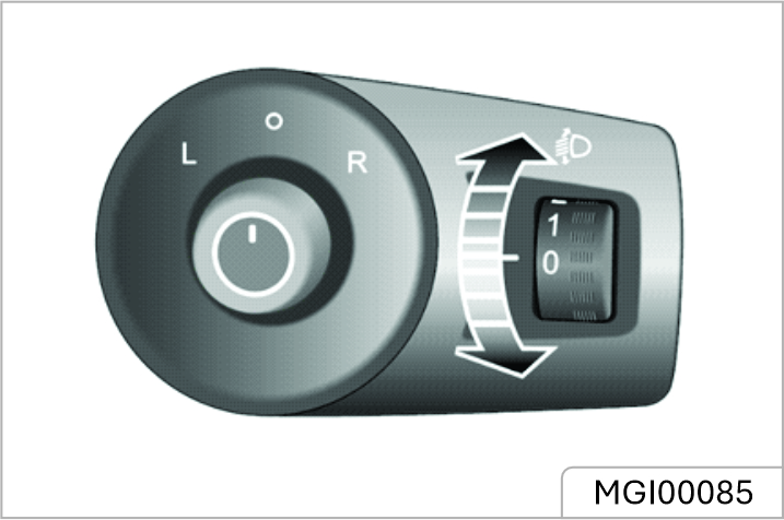
Position 0 is the initial position of the headlamp levelling adjustment switch. The headlamp levelling adjustment can be made as per the following table according to the vehicle load.
| Location | Load |
|---|---|
| 0 | Driver, or driver & front passenger. |
| 1 | All the seats occupied with no load. |
| 2 | All the seats occupied plus an evenly distributed load in the boot, or driver with full load. |
| 3 | Driver only, plus an evenly distributed load in the boot. |
Fog Lamp Switch
Fog lights should only be used when visibility is below 100m - other road users could be dazzled in clear conditions.
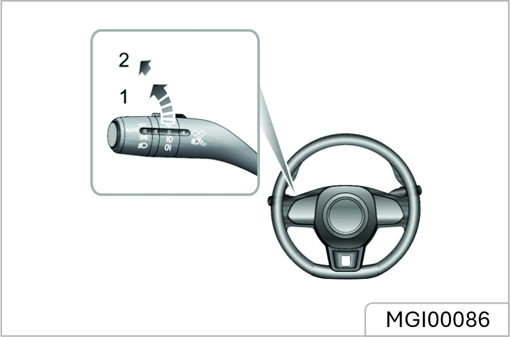
Front Fog Lamps *
With the START/STOP Switch in the ON/RUNNING position and the side lamps on, turn the fog lamp switch to position 1, this will turn on the front fog lamps. The indicator illuminates in the instrument panel when the front fog lamps are on.
Rear Fog Lamp
With the START/STOP Switch in the ON/ RUNNING position and the headlamps or front fog lamps on, turn the fog lamp switch to position 2, this will turn on the rear fog lamp, release the switch to allow it to return to the last position. The indicator illuminates in the instrument panel when the rear fog lamp is on.
Direction Indicator/Main Beam Switch
Take care not to dazzle oncoming vehicles when driving using main beam headlamps.
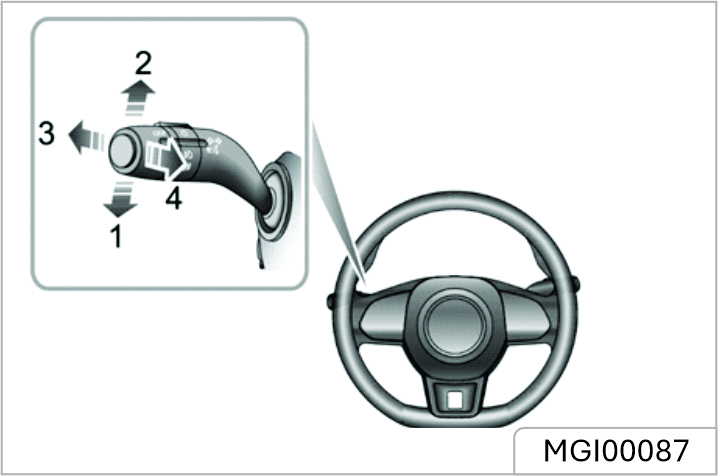
Direction Indicators
Move the lever down to indicate a LEFT turn (1). Move the lever up to indicate a RIGHT turn (2). The corresponding GREEN indicator lamp in the instrument pack will flash when the turning signal lamps are working.
Rotating the steering wheel will cancel the indicator operation (small movements of the steering wheel may not operate the self cancelling). To indicate a lane change, move the lever briefly and release, the indicators will flash three times and then cancel.
Headlamp High/Low Beam Switching
With the START/STOP Switch in the ON position and the master lighting switch turned to position 3, or the auto function has switched the lights on, push the lever (3) towards the instrument panel to turn on headlamp high beams. The high beam indicator lamp in instrument pack illuminates, press the lever (3) again to switch to headlamp low beams.
High Beam Flash
To briefly flash the high beam on and o, pull the lever towards the steering wheel (4) and then release.
Smart Main Beam System *
The smart main beam system serves only as an auxiliary function. The driver must check the status of the front lamps, and turn on the front lamps when necessary.
The smart main beam system serves only as an auxiliary function. The driver must check the status of the front lamps, and turn on the front lamps when necessary.
The Smart Main Beam System is designed to detect the light intensity information of the vehicle in front using the vehicle forward camera and switch the main beam on or o when certain conditions are met. When the smart main beam system is enabled, the smart main beam indicator in the instrument pack illuminates. After the vehicle is started, the smart main beam system enters the ready state of work. In the case of automatic control, the system will automatically turn on the main beam when the surrounding environment is dark and there is no light detected from any vehicles ahead, or oncoming vehicles; when the surrounding environment is bright enough or the system detects the headlamps or tail lamps of the vehicle ahead or oncoming vehicles, the system will automatically turn off the main beam.
To enable the smart main beam system, the following conditions must be met:
If the following conditions are met, the vehicle will automatically exit the smart main beam system.
If the system exits, quickly push the direction indicator/main beam switch (main beam 'ON') towards the instrument pack twice to enter the smart main beam system again. You can only exit two times in one ignition
cycle. If you exit greater than or equal to three times, you will not be able to enable this function again in the current ignition cycle. The smart main beam system can be reactivated after the next ignition cycle
The smart main beam function uses data from the front view camera, always keep the windscreen clean and free from residue in this area to maintain optimum performance of this system. Any damage in this area, such as stone chips must be repaired at the earliest convenience.
Auxiliary Lighting System *
Adding front fog lamps on traditional headlamps, the auxiliary lighting system aims to illuminate the blind zone at the side when the car makes a turn. With this function, the driver can find other vehicles and obstacles in advance, so as to improve the driving safety to a large extent.
Lighting Mode during Cornering
While the car is driving forward, the speed is lower than 40km/h, and the dipped beams are on, turn on the turn signal lamps or allow the steering wheel angle more than 45°, the system will automatically turn on the single side front fog lamp. Turn o the turn signal lamps or allow the steering wheel angle less than 10°, the system will exit from the lighting mode.
Lighting Mode during Parking
While the car is reversing and the dipped beams are on, the system will automatically turn on the front fog lamps on both sides and the reverse lamp. When the vehicle speed is higher than 15km/h, or the reverse lamp is turned o for more than 10s, the system will exit from the lighting mode.
Hazard Warning Lamp
Press the hazard warning lamp button to turn on the hazard warning lamps. The turning signal lamps and direction indicator lamps will flash together. Press the button again to switch o the hazard warning lamps. All turning signal lamps and direction indicator lamps
will stop flashing. For more details and location refer to 'Emergency Information' 'Hazard Warning Devices'
Front Interior Lamp
According to dierent configurations of the vehicles, the front interior lamp has dierent shape
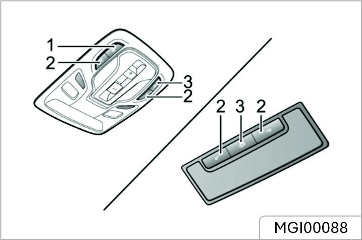
In addition to the manual control of the interior lamps, some operating conditions will activate an automatic control function. Press button 3 to turn on or turn o the automatic control.
Interior light illumination occurs automatically whenever the following occur.
If a door is open for more than a certain period of time, the front interior lamp will be switched o automatically to avoid battery drain.
Rear Interior Lamp*
According to dierent configurations of the vehicles, the rear interior lamp has dierent shape.
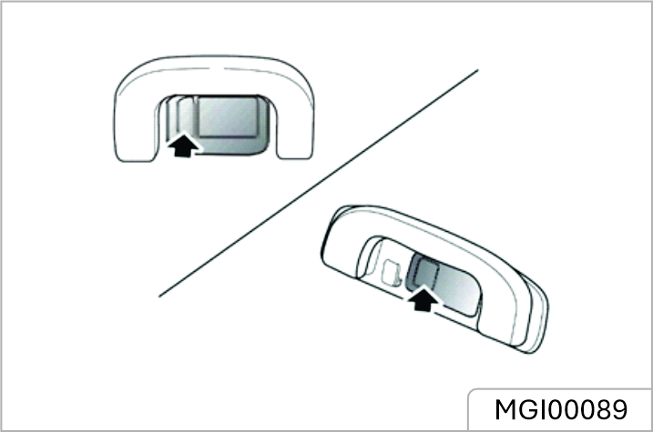
The rear courtesy lights are located on the left and right sides of interior roof panel. Press the lamp lens as indicated in the diagram to switch on the rear courtesy lights, press it again to switch o the lights.
Please ensure the socket blanking plug is inserted when the power socket is not in use. This will ensure no debris or foreign objects enter the socket preventing its use or cause short circuits.
The 12V power socket has a voltage rating of 12V, and the maximum power of 120 Watt, please DO NOT use any electrical appliance that exceeds this rating.
Extended use of the accessory power socket and USB socket when the engine is switched o will cause premature discharging of the vehicle battery.
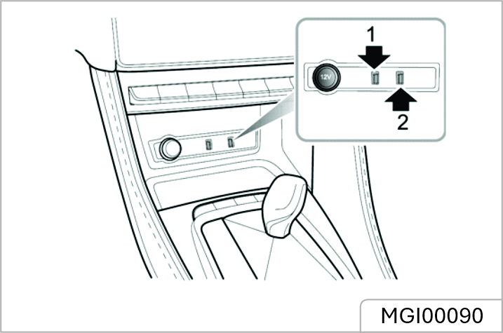
The 12V power socket is located under the shift control knob assembly in the centre console. It can be used as a power supply when the START/STOP Switch is in the ACC or ON/RUNNING positions when the blanking plug is removed. Located to the right of the power socket are two USB ports. Both of them can be used to provide a 5V power supply or a data transmission connection.
The vehicle is not supplied with a cigar lighter. If required, please contact your local JSW MG Authorised Service Center.
There are two USB ports located at the rear of the centre console, these provide 5V voltage when serving as the power outlet
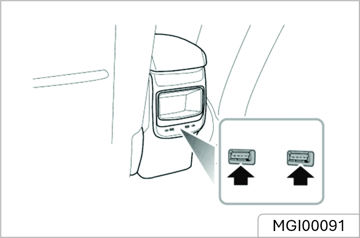
There is also one USB port located in the rear view mirror mounting trim cover, this provides a 5V power source.
Due to dierences in configuration the charging function of the USB port will be slower.
Instructions
Wireless Charging System for Mobile Phones *
The wireless charging function for a mobile phone is realized without the necessity for a connection cable. It is achieved using electromagnetic induction. Wireless Charger in the car can be used to charge Qi certified mobile phones wirelessly. Mobile phone ( Receiver ) controls the power transfer from the Wireless charger in the Car ( Transmitter ). So, Charging rate of the phone will vary based on type/brand of phone used.
The wireless charging function does not apply to all mobile phones, only brands/models with wireless charging function.
For using a mobile phone without wireless charging function, need to use Qi certified accessories/adapter.
Wireless Charging of Mobile Phones
The wireless charging area is located in the area shown in the figure. The charging function is enabled when the START/STOP Switch is placed in the ACC/ ON/ READY positions. Place the phone face up horizontally in the charging area, which can be used for wireless charging. Note: Only one mobile phone can be charged at a time.
Ensure that phone is kept properly on the charging pad. There is possibility of inadequate charging if the mobile phone is not resting properly on the charging pad, in such conditions the phone should be lifted and placed back properly.
Do not keep any metal object in the Charging Pad along with Mobile Phone . It will aect phone charging performance. Also, it may cause overheating of phone and metal objects. Smart phones of some manufacturers may display charging indication on weak current and no increase in net charge. This is due to the particular characteristic of the smart phone and does not imply a malfunction on wireless charging function. For
certain mobile phones with their own protection, the wireless charging speed may decrease sometimes, and the wireless charging may stop.
The wireless charging eiciency may reduce when there is a heavy accessory cover on the smart phone. Items like vehicle Keys, Pen, Coins, Magnetic components such as credit card, telephone card, bankbook, any transportation ticket or any metallic objects should not be kept on Wireless charging pad /over mobile phone while charging. They may get damaged and may also aect mobile charging performance.
When any smart phone without a wireless charging function is placed on the charging pad, it does not aect the vehicle or the smart phone in any way
On bumpy roads, the wireless charging function of the mobile phone may intermittently stop and resume. If the mobile phone deviates from the charging area and stops charging, it will need to be placed back in the rechargeable area.
The size of each brand of mobile phone is dierent, and the position of the charging coil on the mobile phone is dierent. Please adjust the position of the mobile phone accordingly. In addition, the case of some mobile phones may have an impact on wireless charging. It may be necessary to adjust or remove the case to achieve wireless charging.
If the mobile phone cannot be charged correctly, please make sure that there is no foreign matter in the wireless charging area or wait for the wireless charging area to cool down before further attempts. If it still fails, seek the JSW MG Authorised Dealership.
“The wireless cellular phone charging system may not support certain cellular phones, which are not verified for QI specification”
Few wireless chargers cellular phone have limited charging performance, and this is due to inbuilt protection added by phone manufacturers.
Eg. Latest iPhone models have inbuilt Mag safe technology which limits the wireless charging performance.
Glove Box
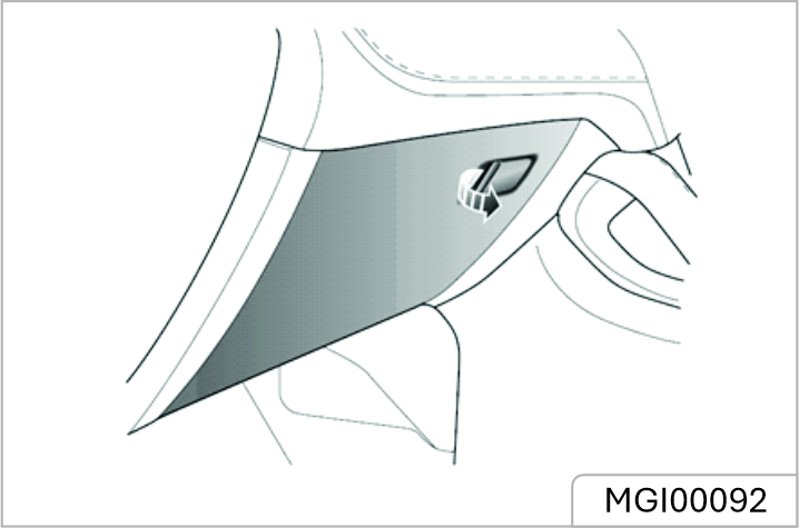
To open the glove box, pull the handle on the glove box cover (as indicated by the arrow). Push the box cover forward to close the glove box. Make sure the glove box is fully closed when the vehicle is in motion
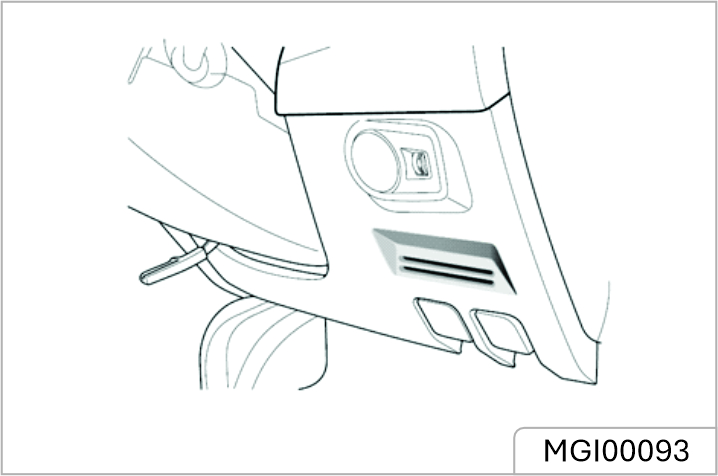
Located in the driver side lower dash trim panel.
Centre Console Armrest Box
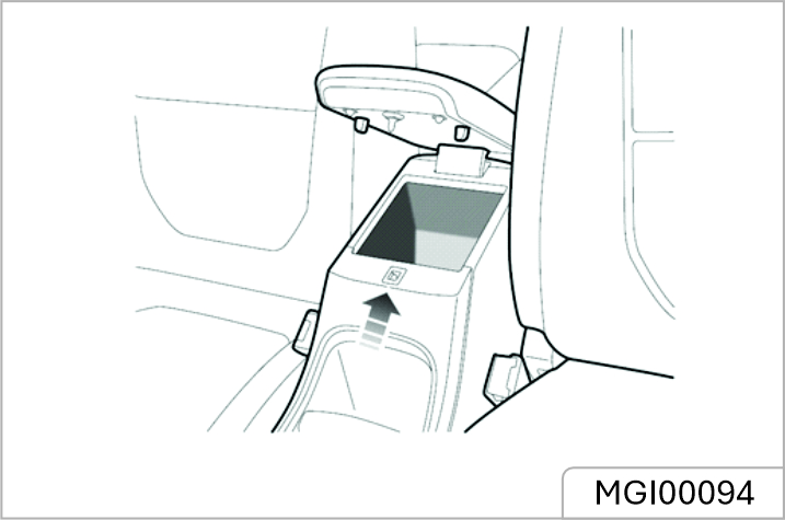
Lift the armrest (arrowed) to open the compartment cover. Put the cover down to close it.
Do not place hot drinks in the cup holder whilst driving. Spillage may result in personal injury or damage.
Centre Console Cup Holder*
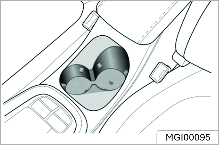
The centre console cup holder is situated at the front end of the centre console armrest assembly.
Rear Armrest and Rear Cup Holder*
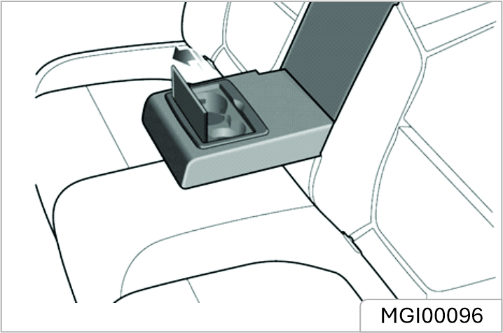
Fold forward to open the rear armrest. There is a cup holder at the front of the armrest. Open the cover to place the cups.
Avoid sudden braking , starting and accelerating of the vehicle when the cup holder is in use to prevent liquid spillage. If hot liquid spills, it can result into burns. Such burn to the driver or co passenger could lead to loss of vehicle control & may result in accident.
Keep your drinks sealed while driving to prevent liquid spillage . Liquid spills may get into vehicles electrical/electronic system & damage electrical/ electronic parts.
When cleaning spilled liquids, do not dry the cup holder at high temperature. This may damage the cup holder.
Pay attention to the following in using the roof luggage rack:
Maximum Authorised Load for the Roof
The maximum authorised load for the roof is 75 kg, this includes the weight of the roof loads and that of the loading equipment installed.
Ensure you are aware of the weight of loads, and weigh them when necessary. Never exceed the maximum authorised load for the roof.
Periodical Check
Always check the condition of the bolt connectors and fastenings before use. Periodically check the bolt connectors and fastenings for security.
Warning Triangle
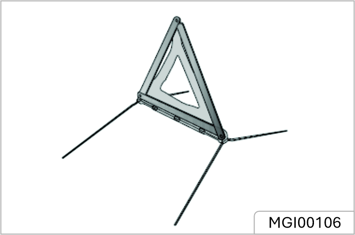
The warning triangle supplied with your car is stowed in the loadspace. If you have to stop your car on the road in an emergency, you must place a warning triangle approximately 50 - 150 metres behind the car, if possible, and press the hazard warning switch to warn other road users of your position.
Using Booster Cables
Using booster cables (jump leads) from a donor battery, or a battery fitted to a donor vehicle, is the only approved method of starting a car with a flat battery. If the battery from a donor vehicle is to be used, the vehicles should be parked with their battery locations adjacent to one another. Ensure that the two vehicles do not touch.
Starting the Vehicle
Ensure that each booster cable connection is securely made. There must be no risk of the clips accidentally slipping from the battery terminals (as a result of engine vibration, for example), this could cause sparking, which could lead to fire or explosion.
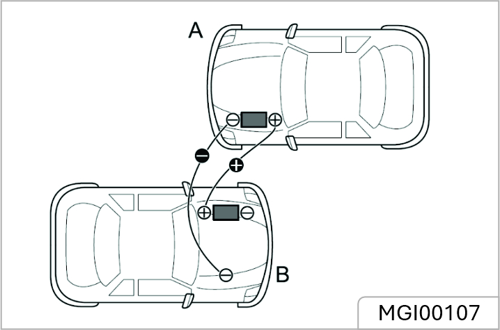
Ensure the START/STOP Switch is turned o and switch o ALL electrical equipment of BOTH vehicles, then follow the instructions below:
NEVER turn on any electrical equipment on the started vehicle before removing the booster cables
It is recommended to ensure that the disabled vehicle runs for more than 1 hour after it is started, in order to recover the battery power.
Towing for Recovery
Towing Hook
DO NOT use a tow rope that is twisted - any untwisting force could unscrew the towing eye.
Your car is equipped with a removable towing hook, that can be used at the front or the rear of your vehicle. The towing hook is stored in the tool kit beneath the loadspace floor when not in use. To fit the towing hook, first press one end of the small cover plate (the white dot in the figure above), then open the small cover plate after the other end is lifted, then screw the towing hook through the small hole into the threaded hole on the bumper beam (as shown in the figure). Ensure the towing eye is fully tightened.
The towing eye cover may be secured to the bumper by a plastic cord.
Both towing points are intended for use by qualified recovery specialists to assist in the recovery of your car when a breakdown or accident occur, such as pulling your vehicle onto the trailer, etc. They are not designed for towing other vehicles, and must NEVER be used to tow a trailer or caravan. The car can be towed by using a soft rope, but a hard rod is preferred.
Towing for Recovery
If, due to an electrical fault, potential safety hazards may exist, it is not allowed to put the START/STOP Switch in the ON position. When towing, DO NOT suddenly accelerate or brake suddenly, this can cause accidents. The towing speed of a vehicle must not exceed 30 km/h, the towing distance shall not exceed 50 km.
Suspended Towing
If your car needs to be towed, most qualified recovery specialists will use wheel lift equipment to suspend the front wheels, while the rear wheels remain on the ground. Ensure the parking brake is released, the hazard warning lamps are activated and no passengers are left in the vehicle.
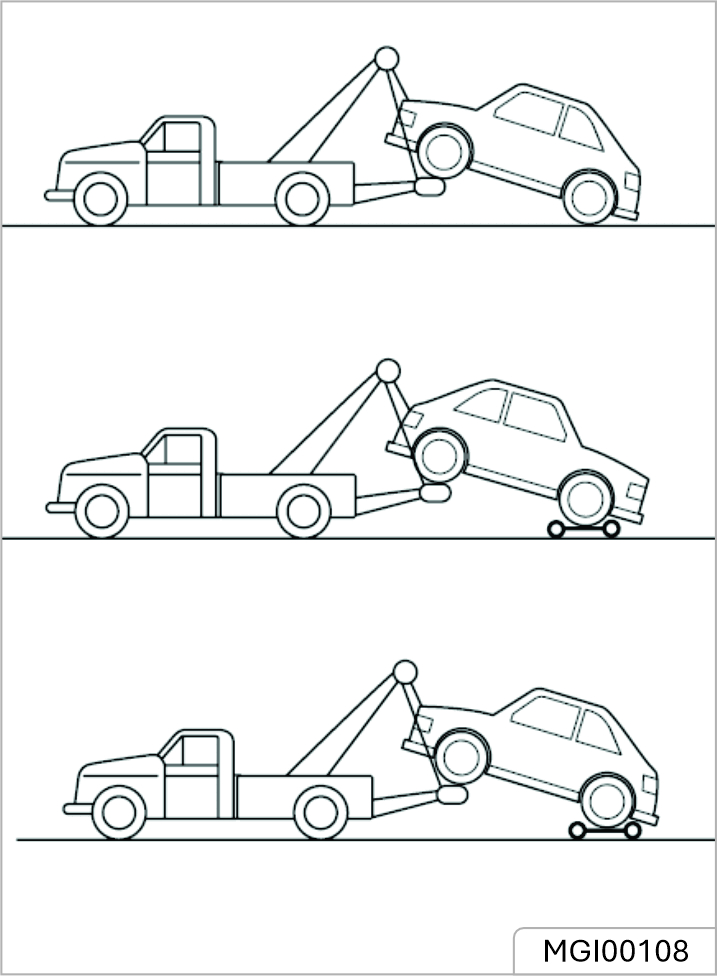
DO NOT tow the vehicle equippedwith CVT with four wheels on theground. This type of vehicle canonly be towed by suspended towing, otherwise the transmission may be damaged.
If vehicle is towed with the four wheels on the ground, observe the following precautions:
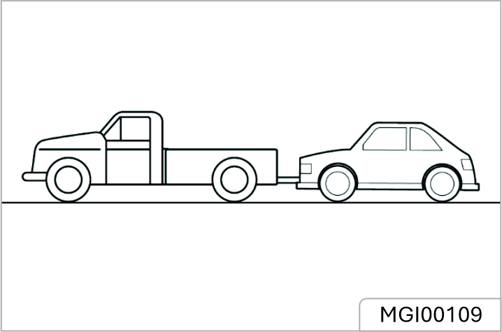
Without the engine running, greater eort may be required to operate the brake pedal and turn the steering wheel. Longer stopping distances will also be experienced.
Transporter or Trailer with Rope
If your car is to be transported on the back of a trailer or transporter, it must be secured as illustrated:
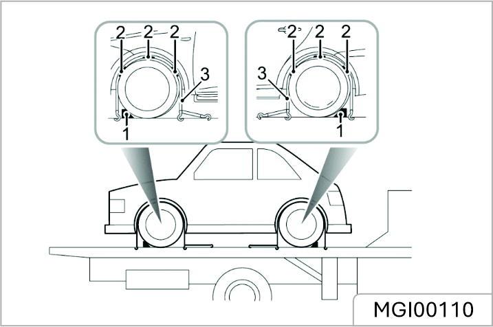
Spare Wheel and Toolbox
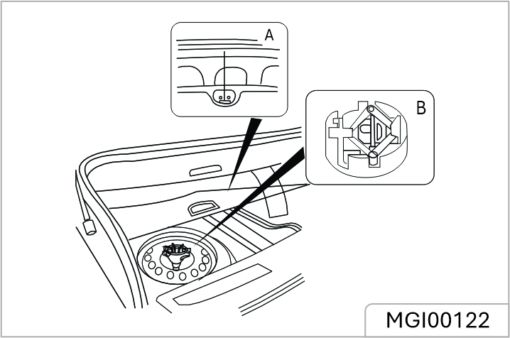
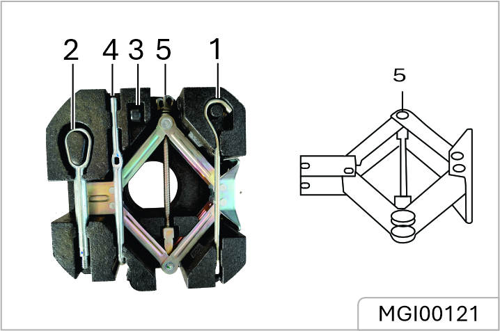
Changing a Wheel
If you need to change the wheel during the journey, choose a safe place to stop away from the main thoroughfare if possible. Always ask your passengers to get out of the vehicle and wait in a safe area away from other traic. Switch on hazard warning lamps. If the conditions permit, place a warning triangle which is approximately 50 to 150 meters away behind the vehicle to warn other vehicles. Before changing a wheel, ensure the front wheels are in the straight ahead position. Apply the parking brake, and place the shift lever in P position.
Observe the following precautions:
Positioning the Jack
NEVER work beneath the vehicle with the jack as the only means of support. The jack is designed for wheel changing only! NEVER jack the vehicle using any jacking points other than the designated points shown. Otherwise, serious damage to the vehicle could result.
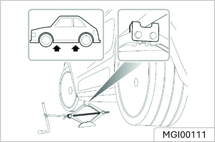
Position the jack on firm level ground under the jacking point nearest the wheel to be removed. Make sure the rectangle slot of the jack must support the vehicle body revers (see the figure).
Turning the jack screw rod handle by hand, raise the jack until the jack head fits snugly on vehicle body revers. Ensure that the base of the jack is in full contact with the ground.
Check the pressure of the spare wheel to avoid flat tyre as it is not used for a long time. Always check tyre pressures after changing a wheel. After replacing the wheel, you must tighten the wheel bolts to the specified torque (120~ 130Nm).
For your safety, please put the spare tyre under the vehicle body flanging area near the jack. Avoid the outer side of the wheel contacting the ground, and the rim surface may be scratched.
Replace the spare wheel with the removed wheel and place it under the vehicle body flanging area near the jack. Avoid the outer side of the wheel contacting the ground, and the rim surface may be scratched.
Fit the spare wheel and tighten the wheel bolts until the wheel is seated firmly against the hub.
DO NOT stand on the handle of the wheel bolt spanner or use extension tube on the handle of the spanner. When replacing the wheel, please fully tighten the bolts in the diagonal sequence in 2 times. Contact an JSW MG Authorised Service Center to replace with a new tyre urgently.
Spacesaver Spare Wheel *
Only one space saver spare wheel can be used at any one time, otherwise the operational performance and brake performance may be reduced, thereby leading to accident or injury to yourself and others. When driving on icy or slippery surfaces it is advised to fit the space saver wheel to the rear of the vehicle to maintain adequate stability. This may mean swapping a front wheel with a rear wheel. Snow chains can not be used on the space saver spare wheel, this can cause damage to the car and snow chain.
When the space saver spare wheel is fitted, the vehicle speed should not exceed 80 km/h. Please have the full-scale tyre repaired and replace the spare wheel as soon as possible. This will extend the life span of the spare wheel for other emergencies.
DO NOT use an automatic car wash when the spacesaver wheel is fitted, the guide rails of the car wash may conflict with the wheel/tyre and cause damage.
Fuse
Fuses are simple circuit breakers which protect the vehicle electrical equipment by preventing the electrical circuits from being overloaded. A blown fuse indicates that the item of electrical equipment it protects stops working. Check a suspect fuse by removing it from the fuse box and looking for a break in the wire inside the fuse. It is recommended to have spare fuses in the vehicle, which can be obtained from a local JSW MG Authorised Service Center.
NEVER attempt to repair a blown fuse. ALWAYS replace a fuse with one of the same rating. If a replaced fuse fails immediately, please contact the JSW MG Authorised Service Center as soon as possible.
Fuse Box
There are two fuse boxes in the vehicle:
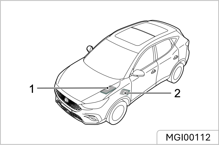
Passenger Compartment Fuse Box
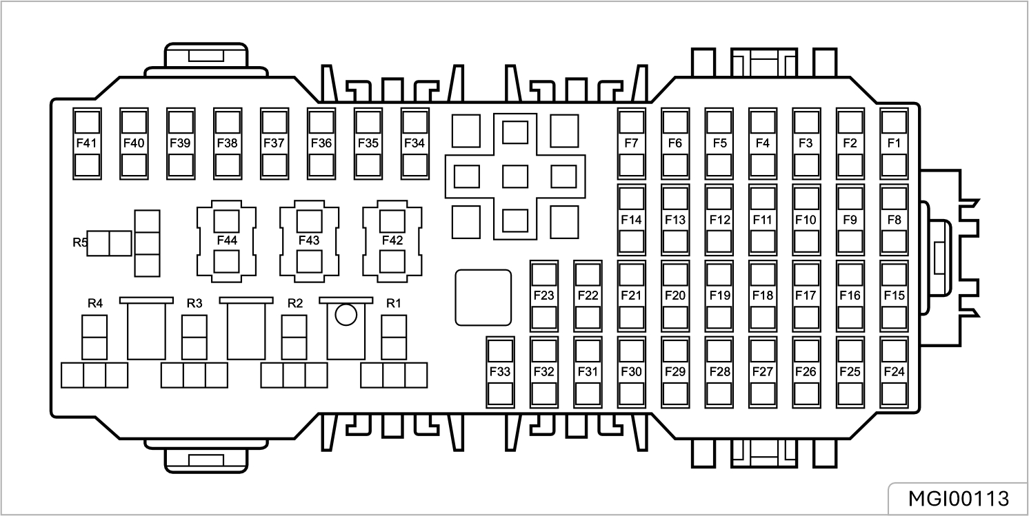
Check or Replace a Fuse
Fuse Specification
| No. | Specs | Function |
|---|---|---|
| F1 | 15A | Front Washer Relay, Rear Washer Relay |
| F2 | 10A | Diagnostic Socket |
| F3 | 5A | PRND Display |
| F4 | - | - |
| F5 | 10A | Airbag ECU (SDM) |
| F6 | 10A | Keyless Start/Stop Switch, Gateway |
| F7 | 30A | Driver Seat Adjust Switch |
| F8-F9 | - | - |
| F10 | 10A | Voice Robot |
| F11-F14 | - | - |
| F15 | 15A | Front Power Socket |
| F16A | 5A | Front Courtesy Lamp, Outside Mirror and Master Light Height Adjust Switch, Top USB, Left Headlamp Assembly, Right Headlamp Assembly |
| F16B | 10A | Front Courtesy Lamp, Outside Mirror and Master Light Height Adjust Switch, Top USB, Left Headlamp Assembly, Right Headlamp Assembly, Rear Courtesy Lamp |
| F17 | 5A | Rear USB |
| F18 | 5A | EPB Switch |
| F19 | 5A | EPB Switch |
| F20 | 5A | Left Rear Driving Assistance Radar |
| No. | Specs | Function |
|---|---|---|
| F21 | 10A | 360° View Module |
| F22 | 10A | Exterior Mirrors Heating Element |
| F23 | 25A | Rear Windscreen Heating Element |
| F24 | 20A | 20A |
| 25 | 10A | Automatic Temperature Controller |
| F26 | 5A | Instrument Pack |
| F27 | 10A | Transmission Control Module-AT/CVT |
| F28 | 5A | Information Faceplate |
| F29 | 30A | Sunroof |
| F30 | 5A | TBOX |
| F31 | 5A | Tyre Pressure Monitoring System |
| F32 | 10A | Electronic Steering Column Lock |
| F33 | 30A | Sunroof |
| F34–F41 | - | - |
| F42 | 25A | Stability Control Module(Valve)-MT |
| F42 | 40A | Stability Control Module (Valve)-AT/CVT |
| F43 | 30A | Passenger Window lift Switch, Rear Left Window Lift Switch |
| F44 | 30A | Driver Door Switch Pack, Driver Window Lifter, Rear Right Window Lift Switch |
Front Compartment Fuse Box
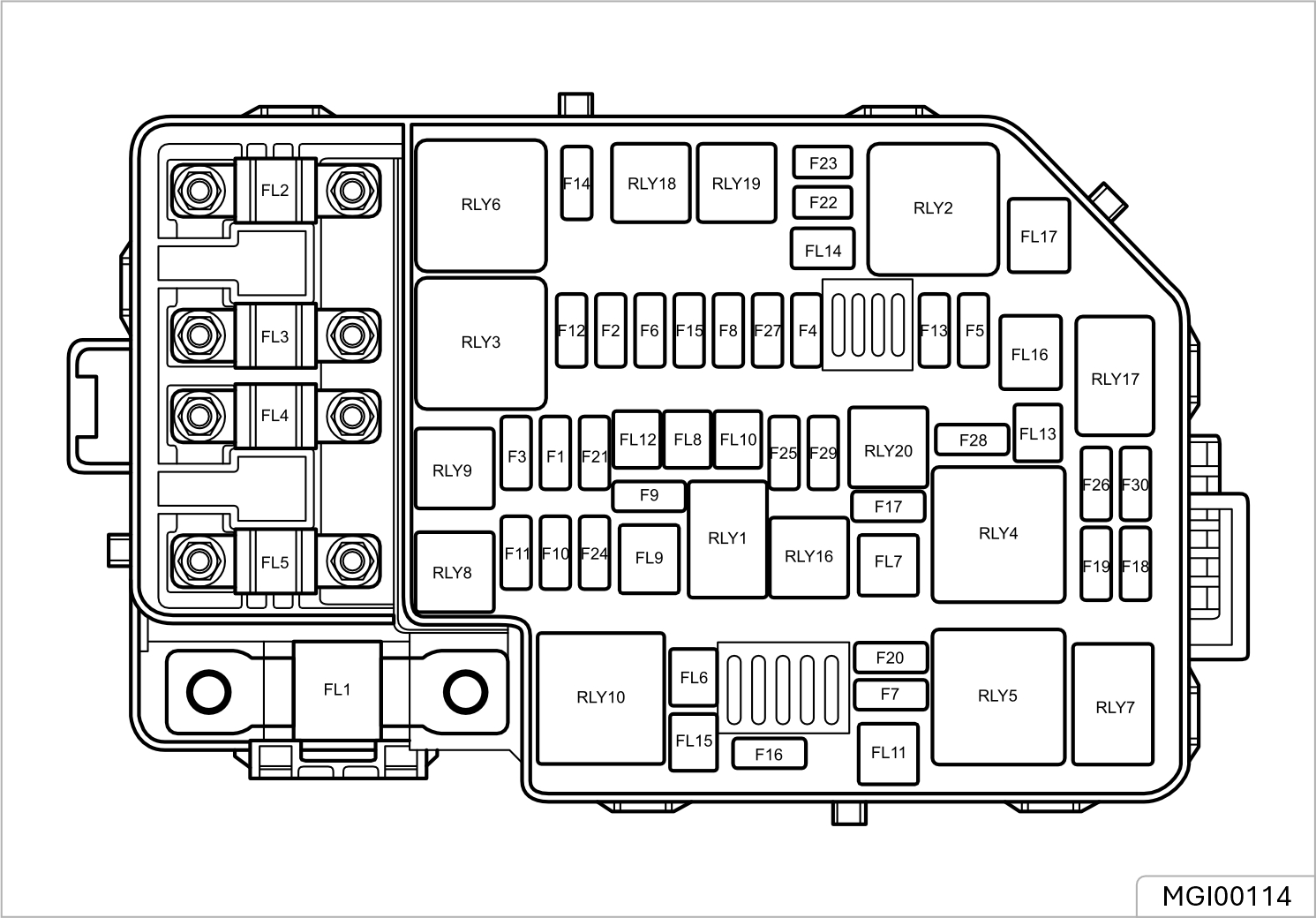
Check or Replace a Fuse
Fuse Specification
| No. | Specs | Function |
|---|---|---|
| FL1 | 150A | Alternator |
| FL2 | 80A | Electric Power Steering Module |
| FL3 | 40A | Cooling Fan Relay Pack |
| FL4 | 80A | Windscreen/Mirror Heating Relay, Passenger Compartment Fuse F18, F19, F20, F21, F42, F43, F44 |
| FL5 | 80A | KLR Relay, Passenger Compartment Fuse F1, F2, F3, F4, F5, F6, F7, F24, F25, F26, F27, F28, F29, F30, F31, F32, F33 |
| FL6 | - | - |
| FL7 | 40A | Automatic Temperature Controller, Blower |
| FL8 | 20A | Body Control Module |
| FL9 | 40A | Stability Control Module(Pump) |
| FL10-12 | - | - |
| FL13 | 30A | Starter Relay |
| FL14 | - | - |
| FL15 | 30A | EVP Relay |
| FL16-17 | - | - |
| F1 | 10A | Right Headlamp Assembly |
| F2 | 15A | Downstream Lambda Sensor, Upstream Lambda Sensor,Canister Purge Valve(1.3T), Purge Washer Pump(1.3T) |
| F3 | 10A | Left Headlamp Assembly |
| F4 | 10A | Compressor Relay |
| F5 | 5A | Engine Control Module |
| F6 | 10A | Fuel Injector |
| F7 | 30A | Front Wiper Enable Relay, Front Wiper High/Low Speed Relay |
| No. | Specs | Function |
|---|---|---|
| F8 | 5A | Cooling Fan Relay Pack, Brake Pedal Switch, Fuel Pump Relay, AC Pressure Switch, Neutral Switch(1.5L), Canister Vent Valve(1.3T), EVP Relay(1.5L) |
| F9 | 20A | Fuel Pump Relay |
| FI0 | 10A | Right Headlamp Assembly |
| F11 | 10A | Left Headlamp Assembly |
| F12 | 30A | Ignition Coil, Engine Control Module |
| F13 | 15A | Horn Relay |
| F14 | - | - |
| F15 | 10A | Intake Variable Camshaft Timing, Exhaust Variable Camshaft Timing, Canister Purge Valve(1.5L), Oil Control Valve(1.3T) |
| F16 | 15A | Rear Wiper Relay |
| F17 | I0A | Fog Lamp Relay |
| F18 | 5A | Airbag ECU (SDM) |
| F19 | 5A | Instrument Pack, Front Detect Radar, Front View Control Module, Shifter Mechanism, Reverse Lamp Switch, Airbag Display Module |
| F20 | 5A | Engine Control Module |
| F21 | 25A | Body Control Module |
| F22-24 | - | - |
| F25 | 30A | Body Control Module |
| F26 | - | - |
| F27 | 15A | Body Control Module |
| F28-29 | - | - |
| F30 | 5A | Engine Control Module, Transmission Control Module-CVT |
Bulb Specification
| Lamp Bulb | Specification |
|---|---|
| Headlamp High/Low Beam | LED |
| Front Direction Indicators | LED |
| Daytime Running Lamps | LED |
| Front Side Light | LED |
| Front Fog Lamps * | * H8 35W |
| Reverse Lamps | W16W 16W |
| Rear Direction Indicators | WY16W 16W |
| Rear Side Light (high configuration) | LED |
| Lamp Bulb | Specification |
|---|---|
| Stop Lamps (high configuration) | LED |
| Rear Side Light (low configuration) | W5W 5W |
| Stop Lamps/ Rear Side Light (low configuration) | W21/5W 21/5W |
| License Plate Lamps | W5W 5W |
| Rear Fog Lamps | LED |
| High Mounted Stop Lamp | LED |
| Interior Lamp | LED |
| Load Space Lamp | C10W 10W |
Bulb Replacement
Before replacing any bulb, turn o the START/ STOP Switch and lighting switch to avoid any possibility of a short circuit.
Take care NOT to touch the glass with your fingers; always use a cloth to handle the bulb. If necessary, clean the glass with methylated spirits to remove fingerprints. If in doubt, when replacing bulbs, contact the JSW MG Authorised Service Center. For replacement of other bulbs not listed please consult the JSW MG Authorised Service Center.
Load Space Lamp Bulb Renewal
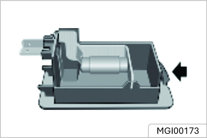
Routine Maintenance
The safety, reliability and performance of your car will depend partly on how well it is maintained. You must ensure that maintenance is carried out when required and according to the information contained in the “Service Schedule” - see www.mgmotor.co.in - owners section.
Servicing *
Some vehicles, for next service information please refer the pop-up reminder massage from mobile application or Entertainment display when service due.
Service History
Ensure your local MG Authorised Service Center fills in the Service Records after each service.
Brake Fluid Replacement
Replace the brake fluid according to the information contained in the “Service Schedule” - see www.mgmotor.co.in - owners section.
Brake fluid replacement will be an additional cost.
Coolant Replacement
Replace the engine coolant (mixed solution of antifreeze and water) according to the information contained in the “Service Schedule” - see www.mgmotor.co.in - owners section.
Coolant replacement will be an additional cost.
Emission Control
Your car is fitted with emission and evaporative control equipment designed to meet specific territorial and legal requirements. Incorrect engine settings may adversely aect exhaust emissions, engine performance and fuel consumption, as well as causing high temperatures, which could result in damage to the catalytic converters and engine
You should be aware that unauthorised replacement, modification or tampering with this equipment by an owner or motor vehicle repairer could result in the manufacturer's warranty being deemed as invalid. In addition, engine settings must not be tampered with.
Owner Maintenance
Any significant or sudden drop in fluid levels, or uneven tyre wear, should be reported without delay. For further information, refer to the JSW MG Authorised Service Center
In addition to the routine services referred to previously, a number of simple checks must be carried out more frequently. You can carry out these checks yourself and advice is given on the pages that follow. Daily Checks
The engine oil level should be checked more frequently if the car is driven for prolonged periods at high speeds.
Special Operating Conditions
If your car is frequently used in dusty conditions, or operated in extreme climates where sub-zero or very high ambient temperatures are normal, more frequent attention may need to be paid to servicing requirements. You need to carry out special maintenance operations (refer to Service Portfolio or contact your JSW MG Authorised Service Center).
Safety in the Garage
Cooling fans may commence operating after the engine is switched o, and continue operating for a number of minutes. Keep clear of all fans while working in the engine compartment.
If you need to carry out maintenance, observe the following safety precautions at all times:
Toxic Liquid
Fluids used in motor vehicles are poisonous and should not be consumed or brought into contact with open wounds. These include: battery acid, coolant, brake fluid, power steering fluid, fuel, engine oil and windscreen washer additives. For your own safety, ALWAYS read and observe all instructions printed on labels and containers.
Used Engine Oil
Prolonged contact with engine oil may cause serious skin disorders, including dermatitis and cancer of the skin. Wash thoroughly after contact. Used engine oil should be disposed of correctly. Incorrect disposal can cause a threat to the environment
Opening the Bonnet
DO NOT drive when the bonnet is not closed or retained only by the safety catch.
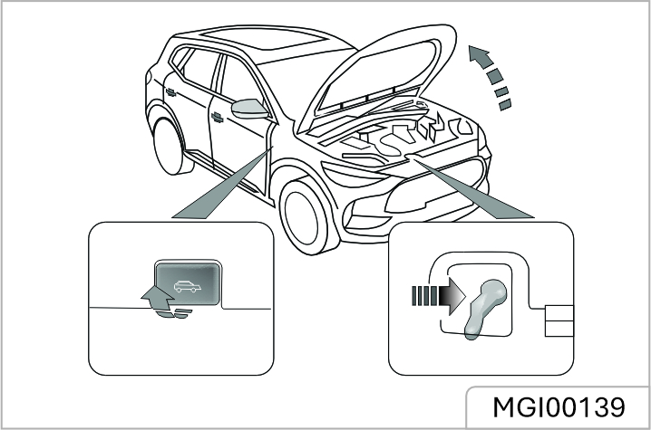
Closing the Bonnet
Support the bonnet by one hand, release the support rod using the other hand, and place it firmly into the support rod base. Then hold the bonnet using both hands and lower it, allowing it to drop for the last 20 cm ~ 30 cm to fully close the bonnet. By attempting to lift the front edge of the bonnet, check if the lock is fully engaged after closing the bonnet. If it is not fully engaged, you must repeat the operation.
Bonnet Open Warning
If the bonnet is not fully engaged, when the vehicle power system is in the ON/ RUNNING position, the corresponding alarm icon will be displayed in the information message centre of the instrument pack. If it is detected that the bonnet is not fully engaged whilst driving, an audible warning will sound.
1.5L Engine Compartment
While working in the engine compartment, always observe the safety precautions listed under 'Safety in the Garage', refer to 'Maintenance' in 'Maintenance' section.
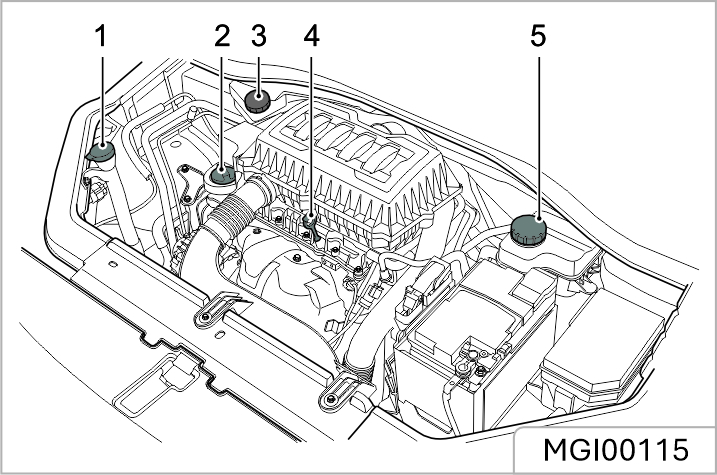
1.3L Turbocharged Engine Compartment
While working in the engine compartment, always observe the safety precautions listed under 'Safety in the Garage', refer to 'Maintenance' in 'Maintenance' section.
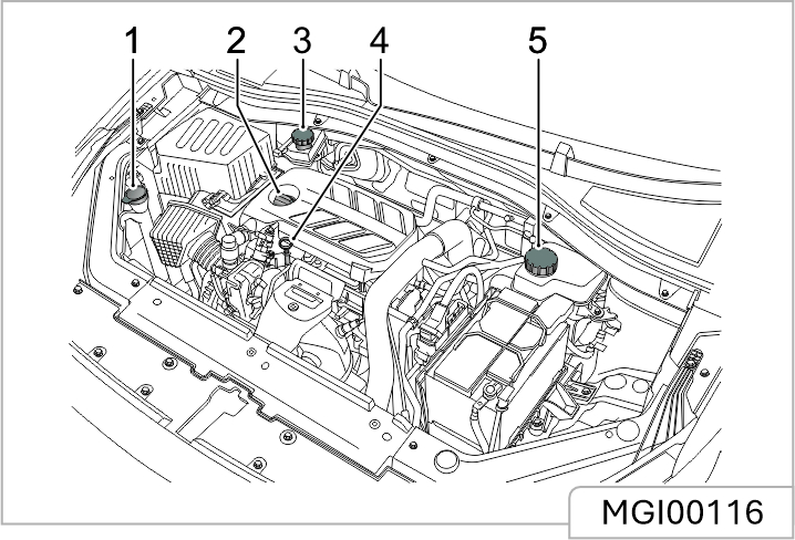
Engine Oil
ACEA Classification of Engine Oils
European Automobile Manufacturers Association (ACEA) will classify the engine oils based on performance and quality. To ensure the best performance of the vehicle, please only use engine oils that are recommended by the manufacturer (see “Technical Data” - 'Recommended Fluids and Capacities'. If you are operating the vehicle in extreme temperature conditions please consult your JSW MG Authorised Service Center for advice.
Engine Oil Level Check and Top Up
Driving the vehicle with the engine oil level ABOVE the upper mark, or BELOW the lower mark on the dipstick, will damage the engine. Take care to avoid spilling engine oil onto a hot engine – a fire may result!
1.3L Turbocharged Engine
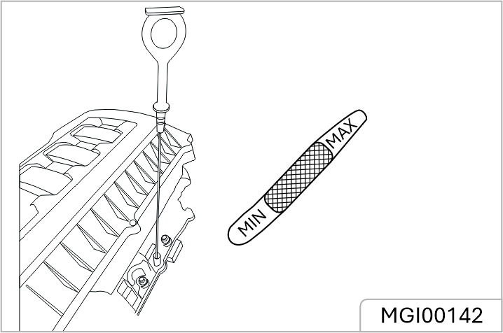
1.5L Engine
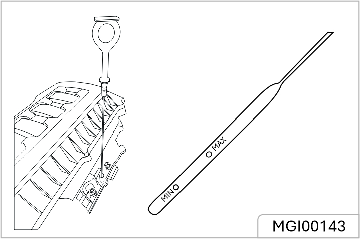
Check the oil level weekly and top up with oil when necessary. Ideally, the oil level should be checked with the engine cold and the car resting on level ground. However, if the engine is running and already getting warm, wait for at least five minutes after switching o the START/STOP Switch before checking the level.
Engine Oil Specification
Use the engine oil recommended and certified by the manufacturer. Refer to “Recommended Fluids and Capacities” in “Technical Data” section.
Do not use the oil additives not applicable to the car, or else the engine may be damaged. You are recommended to use the oil additives certified by the manufacturer, please consult your local Authorised Repairer for details.
Check the engine oil level more frequently if the vehicle is driven at high speed for prolonged periods.
Coolant Check and Top Up
DO NOT remove the coolant pressure cap when the cooling system is hot - escaping steam or hot coolant could cause serious injury
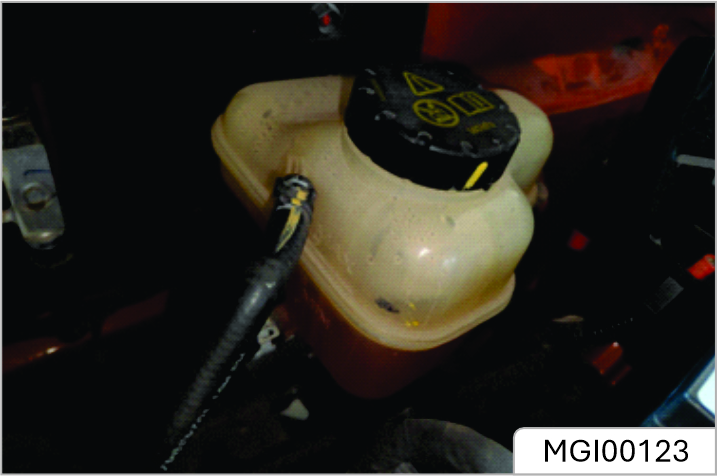
The cooling system should be checked weekly when the cooling system is cold and with the car resting on level ground. If the coolant level is below the “MIN” mark, open the coolant expansion tank cap and top up coolant. The coolant level should not be higher than the “MAX” mark.
Prevent coolant from coming into contact with the vehicle body when topping up. Coolant will damage paint.
If the coolant level falls appreciably during a short period, and you suspect that there may be a leak, please seek an Authorised Repairer for service.
Coolant Specification
The addition of corrosion inhibitors or other additives to the cooling system of this car may severely disrupt the eiciency of the system and cause parts damage. For cooling system issues please consult an Authorised Repairer.
Coolant is poisonous and can be fatal if swallowed - keep coolant containers sealed and out of the reach of children. If accidental contact of coolant by children is suspected, seek medical assistance immediately. Prevent the coolant from coming into contact with the skin or eyes. If this occurs, rinse immediately with plenty of water. If eyes are still red, painful or uncomfortable, seek medical attention immediately.
Brake Pads
DO NOT rest your foot on the brake pedal while driving; this may overheat the brakes, reduce their eiciency and cause excessive wear.
| Brake Pads | Larger than 2mm | |
| Front Brake Disc | 20 ~ 22 mm | |
| Rear Brake Disc | EPB Model | 8 ~ 10 mm |
| Non EPB Model | 7 ~ 9 mm | |
Reasonable usage range of brake friction pair:
For the first 1500 km, you should avoid situations where heavy braking is required. Remember that regular servicing is vital to ensure that all the brake components are examined for wear at the correct intervals, and replaced when required to ensure long term safety and optimum performance during the interval prescribed in Service Portfolio. The car needs to run in for 800 km after the brake pad or disc is replaced.
Brake Fluid Check and Top Up
Brake fluid is highly toxic, keep containers sealed and out of the reach of children. If accidental contact of brake fluid is suspected, seek medical attention immediately. Prevent brake fluid coming into contact with the skin or eyes. If this occurs, rinse immediately with plenty of water. If eyes are still red, painful or uncomfortable, seek medical attention immediately.
The brake fluid level should be checked weekly when the system is cold and with the car on level ground. The brake fluid level can be seen through the reservoir and should be maintained between the “MAX” and “MIN” marks.
Do not allow the brake fluid level to drop below the “MIN” mark or rise above the “MAX” mark.
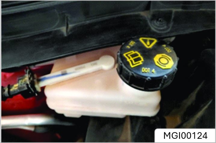
Brake fluid will damage painted surfaces. If you accidentally spill the brake fluid on the painted surface, soak up any spillage with an absorbent cloth immediately and wash the area with water or car shampoo.
Brake Fluid Specification
Use the brake fluid recommended and approved by the manufacturer. Refer to “Recommended Fluids and Capacities” in the “Technical Data” section.
Replace brake fluid regularly according to the Service Portfolio.
Warning notice on battery:
Best Battery Service
To avoid battery discharge, please turn o the ignition switch when leaving the vehicle.
Risk of injury, corrosion, accident and fire exists when operating on vehicle battery and electrical appliance! Wear protective glasses. Prevent acidic or lead particles from falling into eyes, on skin or clothes.
Wear protective gloves and glasses since battery acid is highly corrosive! The battery cannot be turned over because the acid may flow out of the air vent. If the acid splashes into eyes, wash with clean water for a few minutes, then go to see a doctor immediately. If the acid splashes on skin or clothes, immediately neutralize it with rich soap solution and rinse with plenty of water. If you mistakenly drink acid, go to see a doctor immediately. Open flames, electric sparks, strong light and smoking are prohibited! Avoid sparking when handling cables and electrical equipment and removing electrostatic loads. Battery electrode must not be short
circuited because sparks with high energy pose a risk of injury. A battery generates hydrogen gas which is flammable and explosive. Keep any flame or spark away from the vent holes. Battery charging may produce explosive mixed gas, you must ensure that the battery air vent is open to successfully discharge the gas. The battery should be located in a well-ventilated space during charging. Children should be kept away from acid and battery. Turn o the engine, ignition switch and all the electrical appliances before working on electrical appliances. Remove the battery negative cable. Turn o the lamp in bulb replacement. Please pay attention to the polarity of power supply. Check if the polarity of power supply matches before energizing. Each energizing period should not be less than 5 seconds, to avoid frequent or fast on and o operation. Turn o all the electrical appliances before energizing the
battery again. First connect the positive cable, then the negative one. Do not connect the wrong cable - Risk of fire! Unauthorized removal and installation of battery are prohibited, because in some cases, this operation will lead to serious damage to the battery and fuse box. Please contact Service Dealer. Do not disconnect the battery when the ignition switch is on or the engine is running, otherwise it may damage the electrical appliances (electrical components). To prevent the battery case from being exposed to ultraviolet light, do not expose the battery to sunlight. Never attempt to dismantle a battery, they are sealed units. While removing the battery, always disconnect the negative terminal first. And while installing the battery, ensure the negative terminal is connected last. If the battery has been disconnected or a new battery has been installed, the preset radio (if equipped) stations will get reset, once the battery is reconnected.
Battery Specifications
| Vehicle Type | Petrol |
|---|---|
| Rating | 12V 75Ah |
| Technology | Lead Acid Battery |
| CCA | 675 A |
| Dimension | 277(L) x 174(W) x 190(H) |
| Supplier | Exide |
Battery Spec/ratings may vary for Replacement case, please contact JSW MG authorised service center.
Battery Maintenance
For dierent battery types equipped, on the top of some batteries there is a battery condition indicator. Examine the indicator periodically to check the battery's condition. When the indicator shows:
Please ensure a clear view of the condition indicator. Use a torch if natural light is poor. It is recommended to start the vehicle for half an hour every week to help extend the service life of the battery. If the vehicle is stored for more than 1 month, remove the negative terminal from the battery. Make sure that the vehicle power system has been turned o before connecting or disconnecting the negative terminal.
Car Parking Period
If the vehicle is to be parked for an extended period of time, the static current electrical appliance (like clock, security devices) will drain the battery, and the battery has to be recharged. To avoid such case, charge the battery or disconnect the battery negative cable during the vehicle parking.
Please pay attention to the warnings & instructions for battery before working on it.
Always turn o the ignition switch when parking, otherwise, it will greatly reduce the parking time.
Battery Charge with Ground Equipment
Don't charge the frozen battery for the risk of explosion. Even if the battery has been unfrozen, battery acid may still overflow, resulting in corrosion damage. The frozen battery must be replaced.
Turn o the ignition switch and all electrical appliances before charging. If the vehicle has been stored for an extended period of time, and can not be started due to battery undercharge (general terminal voltage ≤ 12V), the battery must be removed from the vehicle and charged with ground equipment (operating in accordance with the charging device manufacturer's instructions). When charging with a low current (such as a small charging device), generally it is not required to remove the battery connecting cables. But you must pay attention to the instructions given by the charging equipment manufacturer. Before the quick charge, that is, before the high current charge, you must remove two connecting cables.
Checking the Electrolyte Level Check the electrolyte level and specific gravity at specific PMS intervals. Check proper electrolyte levels for all the cells. If the level is below the lower marker, add distilled water until the level reaches the upper marker.
Adding distilled water:
Battery Removal
Turn o the ignition switch and all electrical appliance before removing the battery. To remove the battery, you should first remove the negative cable, next the positive cable, and then remove bolts on the battery retaining bracket , finally remove the battery.
Battery Replacement
Please go to an MG Authorised Service Center to remove and refit the battery. Please note that the ignition switch and the electrical appliance have been turned o when installing the battery.
Only fit MG recommended battery while replacement to maintain the correct vehicle functionality. Battery needs to dimensionally OK, to avoid terminals fouling with Battery Tray.
The used battery should not be discarded at will, for it is harmful to the environment. It must be recycled by approved agencies. Please consult the JSW MG Authorised Service center for more details.
Battery Installation
Turn o the ignition switch and all electrical appliance before removing the battery. Place the battery in the mounting position and secure it with battery bracket. Secure the positive cable then the negative one, then energize the battery.
To avoid battery discharge, please turn o the ignition switch when leaving the vehicle Do not leave the power tailgate open for a long period of time. This may drain the battery. Unauthorized Electrical Devices The vehicle can detect selfdischarge of the battery due to over-current that is generated by unauthorized electrical devices such as dashboard camera (dash cam) mounting during parking. If the warning continues even after external electrical devices are removed, have your vehicle inspected by a professional workshop. Accessories - All accessories connected to the battery powered outlets should be removed o
turned o when the vehicle is not in use to protect the battery against discharge. It is advisable to avoid use of any 12V vehicle systems & accessories such as Power tail gate, Sound system, Interior & Exterior lamps, AC Blower, ….etc when engine is switched o. This may cause 12V battery to drain faster.
The JSW MG Motor shall not be liable/ responsible for any damages/injuries, including consequential damages/injuries, resulting due to fitment of nonOEM approved batteries.
Windscreen Washer Check and Top Up
Windscreen washer fluid is flammable. DO NOT allow windscreen washer fluid to come into contact with naked flames or sources of ignition. When filling the washer fluid, DO NOT let the washer fluid spill on parts in the compartment or on the paint surface of vehicle body. In case the washer fluid is spilled on hands or other parts of the body, please immediately wash with clean water
Check the washer fluid level regularly. When the level of washer fluid is low, please top up the washer fluid as instructed. Use the washer fluid recommended and certified by the manufacturer. Refer to 'Recommended Fluids and Capacities'.
DO NOT use anti-freeze or vinegar/ water solution in the washer reservoir - anti-freeze will damage paintwork while vinegar will damage the washer pump.
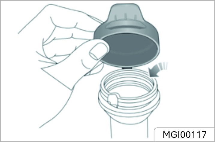
Washer Nozzles
Operate the washers periodically to check that the nozzles are clear and properly directed. If the nozzle is obstructed, insert a needle or thin metal wire into the hole to remove the obstruction.
Wiper Blades
Replacing Front Wiper Blades (Without frame) *
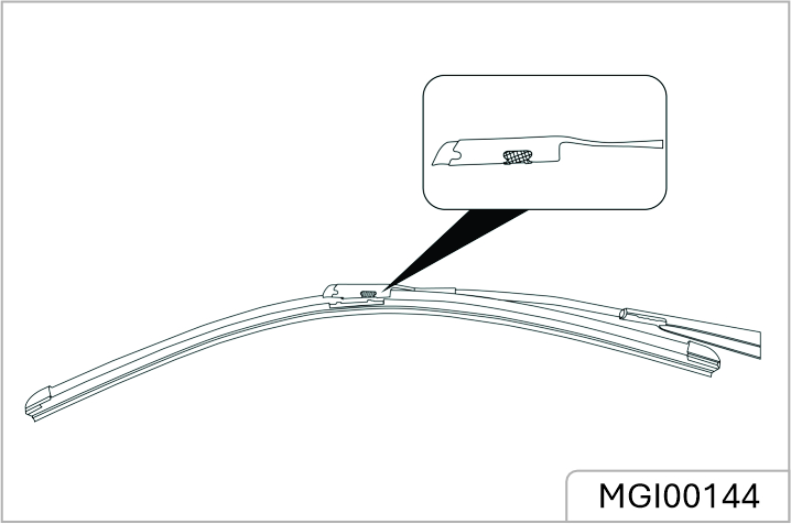
Replacing Front Wiper Blades (With frame) *
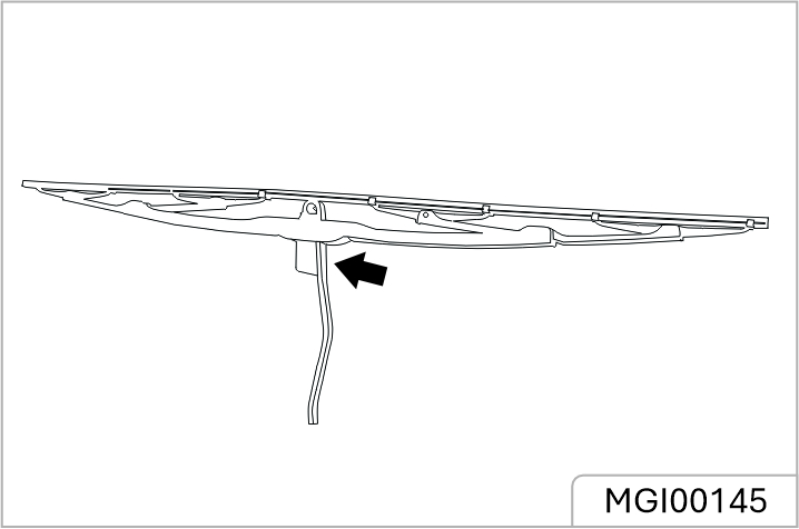
Replacing Rear Wiper Blades
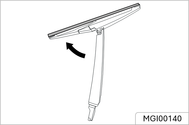
Overview
How to check
Use a good quality tyre pressure gauge to check tyre pressure. You can not tell if your tyres are properly inflated simply by looking at them.
Radial tyres may look properly inflated when they are underinflated. Remove the valve cap from the tyre valve stem. Press the tyre gauge firmly onto the valve to get a pressure measurement. If the cold tyre inflation pressure matches the recommended pressure on the tyre and loading information label, no further adjustment is necessary. If the pressure is low, add air until you reach the recommended pressure. Make sure to put the valve caps back on the valve stems. Without the valve cap, dirt or moisture could get into the valve core and cause air leakage. If a valve cap is missing, install a new one as soon as possible.
If you overfill the tyre, release air by pushing on the metal stem in the centre of the tyre valve. Recheck the tyre pressure with the tyre gauge. Be sure to put the valve caps back on the valve stems. Without the valve cap, dirt or moisture could get into the valve core and cause air leakage. If a valve cap is missing, install a new one as soon as possible
New Tyres
New tyres may not have the best adhesive ability at the beginning. Therefore, driving your vehicle at moderate speed and in a prudent way at the first 500 kilometres, which is also beneficial to the service life of the tyres. The damage of tyre or rim may happen unnoticed. If abnormal vibration or handling is experienced, that means the tyre or rim may have been damaged. Please slow down and park your vehicle in absolute safety, then check the tyre and rim. If you can't see the damage from the outside, you should continue to drive with low speed and go to the nearest JSW MG Authorised Service Center for inspection.
Directional Tyres
Directional tyres are marked with 'direction of rotation' (DOR). To maintain handling characteristics, tyre performance, low road noise and extend tyre life, tyres must always be fitted with indication arrow showing the correct 'DOR
Tyre Life
Correct tyre pressure and moderate driving style can extend tyre life. Recommendations:
Tyre Pressure
Incorrect pressure will cause the abnormal wear of the tyre, greatly shorten the service life, and have an adverse eect on the driving characteristics of the vehicle. Tyre pressure should be checked at least once a month, and once prior to each long-distance journey
Driving Style
Excessively harsh acceleration and braking (you may hear a piercing noise) or driving at high speed whilst cornering will increase the wear of tyre.
Wheel Balance
The working balance of auto-wheels is well tested before a new vehicle comes out of the factory. But the wheels may be out of balance due to many factors. If wheels are out of balance, shaking or vibration of the steering mechanism may occur and the tyres may be excessively worn. It is important to rectify this quickly. Each wheel should be rebalanced after installing a new tyre or having the tyre repair.
Wheel Alignment
Incorrect wheel alignment can cause excessive tyre wear and aect vehicle safety. If the tyres show signs of abnormal wear, seek advice from the JSW MG Authorised Service Center.
Caring for Your Tyres
DEFECTIVE TYRES ARE DANGEROUS! DO NOT drive if any tyre is damaged, is excessively worn, or is inflated to an incorrect pressure.
Always drive with consideration for the condition of the tyres, and regularly inspect the tread and side walls for any sign of distortion (bulges), cuts or wear.
If possible, protect tyres from contamination by oil, grease and fuel.
Tyre Pressure
Before a long distance journey, the tyre pressure must be checked.
Check the pressure (including the spare wheel) at least once a month, when the tyres are cold. If it is necessary to check the tyre pressure when they are warm, you should expect the pressure to have increased by 0.3 to 0.4 bar (4.35 to 5.8 psi). In this circumstance, NEVER let air out of the tyres in order to match the recommended pressure (cold).
Valves
Keep the valve caps screwed down firmly - they prevent dirt from entering the valve. Check the valve for leaks (listen for a tell-tale hissing) when you check the tyre pressure.
Punctured Tyres
If a sharp object penetrates the tyre and remains in it, the tyre may not leak. If you are aware of this occurring, reduce speed immediately and drive with caution until the spare wheel can be fitted, or repairs undertaken.
If the sidewall of the tyre is damaged or distorted, replace the tyre immediately, do not attempt a repair.
Tyre Wear Indicators
At the bottom of the original tyre, there is a 1.6 millimeter high wear mark perpendicular to the wheel rolling direction. These indicators moulded into the tread pattern at several points around the circumference. A mark on the side of a tyre, such as the upper case letter TWI or the triangle, indicating the position of the wear mark. When the tread has worn down to 1.6 millimeter, the indicators will come to the surface of the tread pattern, producing the eect of a continuous band of rubber across the width of the tyre.
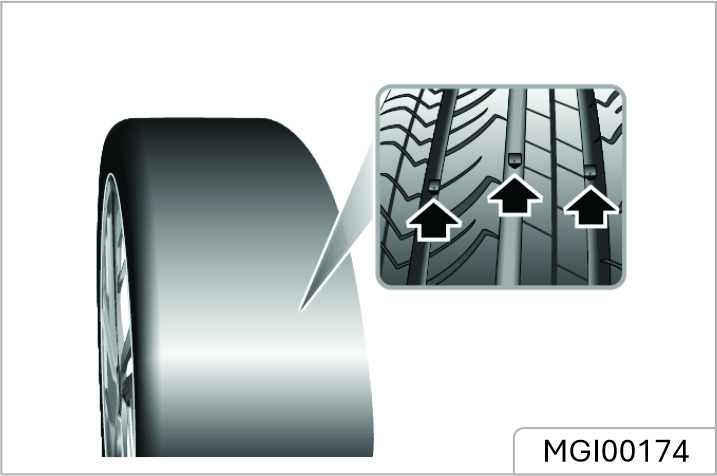
A tyre MUST be replaced as soon as a wear indicator becomes visible.
Wheel Alignment and tyre Balance
The wheels on your vehicle were aligned and balanced carefully at the factory to give you the longest tyre life and best overall performance. In most cases, you will not need to have your wheels aligned again. However, if you notice unusual tire wear or your vehicle pulling one way or the other, the alignment may need to be reset. If you notice your vehicle vibrating when driving on a smooth road, your wheels may need to be rebalanced.
Improper wheel weights can damage your vehicle's aluminium wheels. Use only approved wheel weights.
Replacement Tyres
It is recommended to install the tyres consistent with the original specifications. DO NOT replace the tyres with tyres of any other type. Alternative tyres, of a dierent specification, may adversely aect the vehicle's driving characteristics and safety. In order to make your driving and safety better guarantee, it is suggested that you consult the JSW MG Authorised Service Center.
Always have replacement wheels and tyres balanced before use
Tyre Sidewall Labelling
This information identifies and describes the fundamental characteristics of the tyre and also provides the tyre identification number (TIN) for safety standard certification. The TIN can be used to identify the tyre in case of a recall.
A tyre's sidewall is marked with a tire size designation. You will need this information when selecting replacement tyres for your car. The following explains what the letters and numbers in the tyre size designation mean. Example tyre size designation: (These numbers are provided as an example only; your tyre size designator could vary depending on your vehicle.)
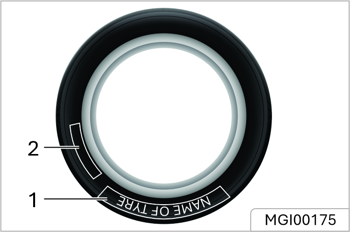
215/55R17 94V
215 - Tyre width in millimetres.
55 - Aspect ratio. The tyre's section height as a percentage of its width
R - Tyre construction code (Radial).
17 - Rim diameter in inches.
94 - Load Index, a numerical code associated with the maximum load the tyre can carry.
V - Speed Rating Symbol. See the speed rating chart in this section for additional information.
Wheel size designation
Wheels are also marked with important information that you need if you ever have to replace one. The following explains what the letters and numbers in the wheel size designation mean.
Example wheel size designation: 17 X 7J
17 - Rim diameter in inches.
7 - Rim width in inches.
J - Rim contour designation.
Tyre speed ratings
The chart below lists many of the dierent speed ratings currently being used for passenger vehicle tyres. The speed rating is part of the tyre size designation on the sidewall of the tyre. This symbol corresponds to that tyre's designed maximum safe operating speed.
| Speed Rating Symbol | Maximum Speed |
|---|---|
| S | 180 km/h (112 mph) |
| T | 190 km/h (118 mph) |
| H | 210 km/h (130 mph) |
| V | 240 km/h (149 mph) |
| W | 270 km/h (168 mph) |
| Y | 300 km/h (186 mph) |
Wheel Fitment Rotation
It is not recommended that you swap wheels from side to side or front to rear in order to equalise tyre wear. Your vehicle is fitted with Tyre Pressure Monitoring System which means that each wheel is programmed to the relative position. When rotating tyres, check for uneven wear and damage. Abnormal wear is usually caused by incorrect tyre pressure, improper wheel alignment, out of-balance wheels, severe braking or severe cornering. Look for bumps or bulges in the tread or side of the tyre. Replace the tyre if you find any of these conditions. Replace the tyre if fabric or cord is visible. After rotation, be sure to bring the front and rear tyre pressures to specification and check lug nut tightness.
Information
Tyres that are asymmetrical or directional can only be installed on the wheel in one direction. The outside and inside of an asymmetrical tyre is not easily distinguishable. Pay careful attention to the markings on the sidewalls of the tyres, noting the "outside" marking and the rotating direction before installing them on the vehicle.
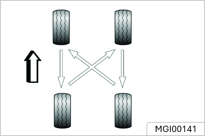
Observe all safety precautions on cleaning products; do not drink fluids and keep them away from the eyes.
External Car
Washing Your Car
Some high pressure cleaning systems will penetrate door, window and sunroof seals, and damage lock mechanisms. DO NOT aim water jets directly at components that might be easily damaged. Do not clean the engine compartment with high pressure water since it may damage the electrical system of the vehicle.
In order to preserve the paint finish on your car, please observe the following care points:
If the car is particularly dirty, use a hose to flush grime and grit from the bodywork, prior to washing. Then, wash the car using cold or lukewarm water containing a good quality wash and wax shampoo. Always use plenty of water to ensure that grit is flushed from the surface and not ground into the paintwork. After washing, rinse the bodywork with clean water and dry o with a chamois leather.
Cleaning the underside
DO NOT use a high pressure hose to clean the engine compartment – damage to the car's electronic systems may occur.
From time to time, but particularly during winter months when salt has been used on the roads, use a hose to wash the underside of the car. Flush away accumulations of mud and thoroughly clean those areas where debris can easily collect (wheel arches and panel seams, for example).
Cleaning with a High Pressure Cleaner
Always read the manufacturers operating instructions.
When using high pressure washers, always ensure there is adequate distance between the spray nozzle and any soft materials, decals or rubber seals.
Removing tar spots
Use white spirit to remove tar spots and stubborn grease stains from the paintwork. Then wash the area immediately with soapy water to remove all traces of the spirit.
Body Protection
After washing, examine the paintwork for damage. If the damage has revealed bare metal,
use a colored primer first, then apply the correct colour base coat and finish o with a lacquer pencil, if appropriate. Carry out this treatment after washing but before polishing or waxing. More extensive damage to paint or bodywork must be repaired in accordance with the manufacturer's recommendations. Failure to do this will invalidate the Anti - Corrosion Warranty. If in doubt, ask your JSW MG Authorised Service Center.
Polishing the Paintwork
DO NOT use car polish containing coarse abrasives – these will remove the paint film and damage the gloss finish.
Occasionally treat the paint surface with an approved polish containing the following properties:
If possible, avoid applying polish or wax products to window glass and rubber seals.
Wiper Blades
Wash in warm soapy water. DO NOT use spirit or petrol based cleaners.
Windows and Mirrors
Regularly clean all windows, inside and out, using an approved glass cleaner.
Windscreen: : In particular, clean the outside of the screen with glass cleaner after washing the car with wash and wax products, and before fitting new wiper blades.
Rear Screen: Clean the inside with a soft cloth, using a side to side motion to avoid damaging the heating elements.
DO NOT scrape or use abrasive cleaners on the inside of the rear screen– this will damage the heating elements
Mirrors:Wash with soapy water. Use a plastic scraper to remove ice. DO NOT use abrasive cleaning compounds or metal scraper.
Plastic Components Any plastic components should be cleaned using conventional cleaning methods and not be treated with abrasive materials.
Paint Damage Any paint damage or stonechips should be treated with suitable paint / lacquer materials immediately to avoid invalidating the Anti Corrosion Warranty.
Weather Strips and Rubber Seals Any weather strips or rubber aperture seals should be treated with suitable materials (silica gel) if they are cleaned using strong detergents, this should avoid any sticking and maintain the service life of the seal.
When cleaning the wheels any materials or water that contact the brake disc directly may eect braking eiciency.
In order to ensure the wheels are kept in optimum condition they should be cleaned regularly. Only use a recommended nonacidic propriety wheel cleaner. Always read the instructions on the product
Cleaning the Interior
Plastic materials
Clean plastic-faced materials with diluted upholstery cleaner, then wipe with a damp cloth.
DO NOT polish dashboard components – these should remain nonreflective.
Carpet and fabrics
Clean with diluted upholstery cleaner - test a concealed area first.
Leather
Clean leather trim with warm water and a non-detergent soap. Dry and polish the leather with a dry, clean, lint-free cloth.
DO NOT use petrol, detergents, furniture creams or polishes as cleaningagents.
Instrument Pack, Audio and Navigation
Display
Clean with a dry cloth only. DO NOT use cleaning fluids or sprays.
Airbag Module Covers
DO NOT allow these areas to be flooded with liquid and DO NOT use petrol, detergent, furniture cream or polishes.
To protect damage to the airbag SRS, the following areas should be cleaned sparingly with a damp cloth and upholstery cleaner ONLY:
Seat Belts
DO NOT use bleaches, dyes or cleaning solvents on seat belts.rniture cream or polishes.
Extend the belts, then use warm water and a non-detergent soap to clean. Allow the belts to dry naturally; DO NOT retract them or use the car until they are completely dry.
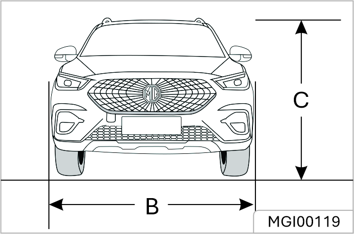
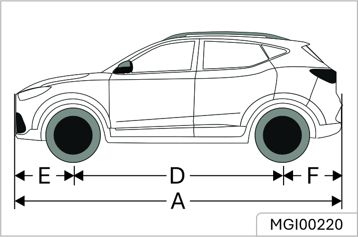
| Item, Units | Item Units Parameter |
|---|---|
| Overall length A, mm | 4323 |
| Overall width B, mm | 1809 |
| Overall height C (unladen), mm | 1628 (excluding luggage rack)/1650 (including luggage rack) |
| Wheelbase D, mm | 2585 |
| Front Overhang E, mm | 901 |
| Rear Overhang F, mm | 837 |
| Front wheel track, mm | 1526 |
| Rear wheel track, mm | 1536 |
| Minimum ground clearance (laden), mm | MT-181/CVT-152/AT-141 |
| Minimum turning circle diameter, m | 11.2 |
| Fuel tank capacity, l | 45/48 |
Vehicle length not including the license plate. Rearview mirrors and the deformed portion of tyre wall directly above the touchdown point are not included in the total width.
| Item, Units | Parameter 1.5L MT |
|---|---|
| Person in cab, person | 5 |
| Unladen vehicle weight (kerb), kg | LV0-1245/LV1-1263/LV2-1271/LV3-1303 |
| Gross vehicle weight, kg | LV0-1678/LV1-1696/LV2-1703/LV3-1736 |
| Unladen front axle weight, kg | LV0-740/LV1-752/LV2-755/LV3-771 |
| Unladen rear axle weight, kg | LV0-505/LV1-511/LV2-516/LV3-532 |
| Laden front axle weight, kg | LV0-847/LV1-859/LV2-862/LV3-878 |
| Laden rear axle weight, kg | LV0-831/LV1-837/LV2-842/LV3-858 |
| Item, Units | Parameter 1.5L CVT |
|---|---|
| Person in cab, person | 5 |
| Unladen vehicle weight (kerb), kg | LV1-1301/LV2-1315/LV3-1349 |
| Gross vehicle weight, kg | LV1-1733/LV2-1748/LV3-1780 |
| Unladen front axle weight, kg | LV1-785/LV2-794/LV3-811 |
| Unladen rear axle weight, kg | LV1-516/LV2-521/LV3-538 |
| Laden front axle weight, kg | LV1-892/LV2-901/LV3-917 |
| Laden rear axle weight, kg | LV1-841/LV2-847/LV3-863 |
| Item, Units | Parameter 1.3T 6AT |
|---|---|
| Person in cab, person | 5 |
| Unladen vehicle weight (kerb), kg | LV1-1317/LV2-1324/LV3-1355 |
| Gross vehicle weight, kg | LV1-1750/LV2-1756/LV3-1788 |
| Unladen front axle weight, kg | LV1-796/LV2-799/LV3-814 |
| Unladen rear axle weight, kg | LV1-903/LV2-905/LV3-921 |
| Laden front axle weight, kg | LV1-892/LV2-901/LV3-917 |
| Laden rear axle weight, kg | LV1-847/LV2-851/LV3-867 |
| Vehicle | Parameter | |
|---|---|---|
| 1.3T | 1.5L | |
| Bore × Stroke, mm × mm | 80×89.4 | 75×84.8 |
| Capacity, Litres | 1.349 | 1.498 |
| Compression ratio | 10:1 | 11.5:1 |
| Fuel type | Regular BSVI petrol min. RON91 (Recommended density of 720 - 775 kg/m2 at 15°C) & Ethanol content ≤ E10 | Regular BSVI petrol min. RON91 (Recommended density of 720 - 775 kg/m2 at 15°C) & Ethanol content ≤ E20 |
| Emission standard | BS6 (OBD-II) | |
# Select the fuel to be added according to the label on the fuel filler port of vehicle's tank. For Petrol Variant -
| Name | Grade | Grade | |||
|---|---|---|---|---|---|
| 1.5L–5P17 | 1.5L–MS35 1 | 1.5L–CVT | 1.3T–6AT | ||
| Engine oil (aftersales replacement), L | C2 5W-30 | 4.1 | 4.6 | ||
| Engine coolant, L | Glycol (OAT) | 5.4 | 6.4 | ||
| Automatic transmission oil, L | AW-1 | - | 6.2 | ||
| Continuously variable automatic transmission oil, L | Continuously variable automatic transmission oil, L | - | 6.96 | - | |
| Manual transmission oil, L | Castrol BOT503 | 1.7 | 1.8 | - | |
| Brake fluid, L | DOT 4 | 0.85 | |||
| Washer fluid, L | ZY-VIII | 4 | |||
| Air conditioning refrigerant, g | R-134a | 540+-20 | |||
| Item | Parameter | |
|---|---|---|
| Front | Camber | -28'±45’ |
| Kingpin Castor | 3°54'±45’ | |
| Toe in (Total) | 8'±15’ | |
| Kingpin Inclination | 11°49'±45’ | |
| Rear | Camber | 1°15'±45’ |
| Toe in (Total) | 24'±20’ | |
| Wheel size | 7J×17 | 6.5J×16 |
|---|---|---|
| Tyre size | 215/55 R17 94V | 215/60 R16 95H |
Spare Tyre
| Wheel rim specification | 6.5J×16 |
|---|---|
| Spare tyre specification | 215/60 R16 |
| Wheels | Unladen |
|---|---|
| Front Wheels | 220kPa/2.2bar/32psi |
| Rear Wheels | 220kPa/2.2bar/32psi |
It is recommended that the pressure of full-size spare tyre should be consistent with that of main tyre.
Terms & Conditions
1. Warning:
Your JSW MG MOTOR vehicle is manufactured to meet the regulations and environmental requirements for Indian conditions. In case you relocate it to any other country than INDIA, it may be very diicult to make modifications to comply with the regulations and environmental requirements of that country and it may be diicult to perform repair service in that country. Please note that a vehicle relocated to any other country than India shall not be covered by the warranty.
| Sr.No. | Category | Warranty Period |
|---|---|---|
| 1 | Complete Vehicle excluding wear & tear parts. |
Personal: 3 years or Unlimited kilometers (whichever is earlier) Commercial: 3 years or 1,00,000 kms (whichever is earlier) |
| 2 | 12V Battery | 1 year starting from date of vehicle delivery (To be provided by Battery manufacturer) |
| 3 | Tyre | 1 year starting from date of vehicle delivery (To be provided by Tyre manufacturer) |
| 4 | Infotainment/ Audio system including T-Box | 3 year starting from date of vehicle delivery |
| 5 | AC Charger | 1 year starting from date of vehicle delivery |
| 6 | Wear & Tear Parts (drive belts, hoses, wiper blades, fuses, clutch disc, brake shoes, brake pads, cables and all rubber parts etc.) | No warranty |
2. The JSW MG Motor New Vehicle Warranty
2.1 Duration of JSW MG Motor's New Vehicle Warranty:
Vehicles in the JSW MG Motor range, delivered as new from 1st April 2019 to the Customer by an authorized JSW MG Motor DEALER, are warranted against any material, assembly or Manufacturing Defects by the Manufacturer. The New Vehicle shall be covered under a Warranty by JSW MG Motor for a period of
2.2 The period of warranty on the vehicle shall not be deemed to be extended by repairs or replacements of any parts.
2.3 In the event the Original Purchaser of the vehicle transfers the vehicle during the period of warranty, it shall be obligation of the subsequent purchaser to notify and inform JSW MG Motor or its authorized dealer of such transfer.
If the vehicle identification number (VIN) of an insured vehicle is declared as total loss by the insurer, any Warranty, Extended Warranty, free services, i-call, e-call and i-smart app (facilities if applicable) provided in respect of such vehicle shall become null and void with effect from the date, if VIN of such vehicle is declared as total loss by the insurer.
Field of Application:
2.4 The customer is covered for:
2.4.1 Free repair (parts, consumables and labour) of any material or assembly defect duly found in the vehicle, at their own request, as well as any repairs on damage caused by this defect to other vehicle parts.
2.4.2 24/7 assistance services as defined in the “JSW MG MOTOR Road Side Assistance” section.
2.5 Parts not covered under warranty conditions contained herein:
The following are the parts not covered by warranty conditions contained herein. Hence, it is requested to contact your nearest JSW MG Motor Dealer for more details.
2.5.1 It is the authorized JSW MG MOTOR EV Dealer's discretion to decide whether it is appropriate to repair or replace the defective part with new part(s), whilst keeping the customer informed.
2.6 The JSW MG Motor New Vehicle Warranty does not cover and JSW MG Motor India Private Limited (JSW MG Motor) and / or JSW MG Motor authorized workshop shall not be responsible for the following:
2.6.1 Normal maintenance services other than 3 free services*, including without limitation, cleaning and polishing, minor adjustments, engine tuning, oil top-up / fluid changes, Diesel Exhaust Fluid (DEF) top-up / replacement, filters replenishment, fastener retightening, wheel balancing, wheel alignment and tyre rotation etc.
2.6.2 The indirect and remote consequences of any fault (loss of operation, duration of immobilization, etc.);
2.6.3 Vehicle components which have undergone conversion work, and/or specification and design changes and the consequences (deterioration, premature wear and tear, alterations, etc.) of the conversion work on other vehicle parts or components, or on its specifications; JSW MG Motor New Vehicle Warranty *The right is reserved to change number of free services at any time without prior notice.
2.6.4 The costs incurred by the Customer for routine maintenance;
2.6.5 Replacement of parts due to normal wear and tear resulting from use of the vehicle or from its mileage including but not limited to clutch, shocker absorbers, wiper blades, brake drum, brake disk, brake pads, brake shoe, lamp, plugs, belts, linings, bulbs, fuses, suspension parts, mountings, parts made of rubber, etc. Other parts, not limited to steering wheel, gear knobs, gear bellows prone to normal wear & tear will have a limited coverage**
2.6.6 Damage or failure resulting due to the following causes:
2.6.6.1 Poor vehicle maintenance, in particular if the instructions for the treatment, the frequency of maintenance or care to be applied to the vehicle set out in the Owner's Manual have not been observed;
2.6.6.2 Due to lack of use / operation of vehicle over prolonged period[s];
2.6.6.3 Misuse, abuse, negligence, improper driving habits, theft etc. of the vehicle;
2.6.6.4 Damage from stress, like use of vehicles in races, rallies or as taxis.
2.6.6.5 Use of parts other than JSW MG Motor Genuine Parts.
2.6.6.6 Any device and / or accessories not Supplied / Fitted by JSW MG Motor.
2.6.6.7 Modifications, alterations, tampering or improper repair.
2.6.6.8 Parts used in applications of which they were not designed or not approved by JSW MG Motor.
2.6.6.9 The vehicle in which the odometer has been tampered with, changed aftermarket or been disconnected.
2.6.6.10 Slight irregularities not recognized as affecting quality or function of the vehicle or parts, such as slight noise or vibrations, or items considered characteristic of the vehicle.
2.6.7 Damage caused by the following external causes:
2.6.7.1 Accidents, impacts, scratches, scoring, projection of gravel or solid bodies, hail, acts of vandalism;
2.6.7.2 Failure to observe the Manufacturerrecommendations;
2.6.7.3 Deposits due to atmospheric pollution, plant-based deposits such as resin, animal-based deposits such as bird droppings, chemical deposits;
2.6.7.4 Transportation of the vehicle;
2.6.7.5 Using an adulterated / incorrect fuel;
2.6.7.6 Fitting accessories not approved by the manufacturer;
2.6.7.7 Fitting accessories approved by the manufacturer, but installed without observing the recommendations defined by the manufacturer;
2.6.7.8 Damage due to airborne fallout, industrial fall out, acid rain, hail and wind storms, or other force majeure events like lightning, fire, floods, earthquakes, war, riots, attacks etc.;
2.6.7.9 Damage caused due to hydro-static lock, submerged vehicle.
2.6.7.10 Damage caused due to rodents;
2.6.7.11 Paint scratches, dents or similar paint or body damage.
2.6.7.12 Incidental or consequential damages, including without limitation, loss of time, inconvenience, loss of use of vehicle or commercial loss.
How does the JSW MG Motor New Vehicle Warranty work?
2.7 To be eligible for the JSW MG Motor New Vehicle Warranty, the Customer must:
2.7.1 have the defect covered by the JSW MG Motor New Vehicle Warranty confirmed as soon as possible, by a JSW MG Motor authorized workshop in writing. If the vehicle is un-roadworthy, the customer must contact the nearest JSW MG Motor authorized workshop member or JSW MG Motor Assistance.
2.8 The JSW MG Motor New Vehicle Warranty does not apply, and JSW MG Motor and JSW MG Motor authorized dealer members are exempt from all liabilities, if:
2.8.1 The vehicle has been driven under conditions not in accordance with those stated in the Owner's Manual (example but not limited to: vehicle overloaded or taking part in any type of sports competition, etc.);
2.8.2 The defect observed is due to the Customer having had the vehicle repaired or serviced in a workshop outside the JSW MG Motor authorized network and not observing JSW MG Motor's recommendations on the subject.
2.9 By way of consideration for the parts supplied by JSW MG Motor under the JSW MG Motor New Vehicle Warranty, parts replaced under this warranty, shall legally become the property of JSW MG Motor.
2.10 All operations, parts and labour, carried out under the JSW MG Motor New Vehicle Warranty are guaranteed until the new vehicle warranty expires.
2.11 Transferring ownership of the vehicle shall not alter the application conditions of the JSW MG Motor New Vehicle Warranty.
3. The JSW MG Motor Anti-corrosion Warranty:
3.1 Duration of the Anti-Corrosion Warranty: This warranty will apply from the delivery date given on the Owner's Manual for a period of:
3.2 Geographical Coverage: The geographical coverage of the Anti- Corrosion Warranty is identical to that for the JSW MG Motor New Vehicle Warranty.
3.3 Anti-Corrosion Warranty field of application
3.3.1 In addition to the JSW MG Motor New Vehicle Warranty, JSW MG Motor guarantees the bodywork and sub frame of JSW MG Motor vehicle Schedule I from perforation from the interior, due to steel panel corrosion caused by a manufacturing, material or protective product application defect.
3.3.2 This guarantee covers the repair or replacement of components with perforated steel panel work due to a manufacturing, material or protective product application defect, acknowledged by the Manufacturer.
3.3.3 It is authorized JSW MG Motor workshop's discretion to decide whether it is appropriate to repair or replace these components, and to inform the Customer.
3.4 The JSW MG Motor Anti-Corrosion Warranty does not cover:
3.4.1 any damage which is not covered by the JSW MG Motor New Vehicle Warranty, as defined at the start of this booklet; Mechanical components which are not an integral part of the bodywork or sub-frame (wheel rims, exhaust system, etc.).
3.4.2 In case, repairs (including denting or painting) have been carried out on the body of the JSW MG Motor Vehicle in a workshop outside the JSW MG Motor authorized network.
3.5 Anti - Corrosion Warranty conditions of application
3.5.1 To obtain the Anti-Corrosion Warranty, the Customer must contact any Workshop of the JSW MG Motor Authorized Workshop Network - only such Workshop have authorization for operations of this sort
3.5.2 Application of the JSW MG Motor Anti-Corrosion Warranty is subject to the anti-corrosion tests on the bodywork and sub frame. Customer shall ensure that these tests are conducted at the mileage intervals stated in the Owner's Manual, and at least once every two years. Scheduled maintenance services in the JSW MG Motor authorized workshop network incorporate these tests.
3.5.3 If the Customer requests to have the anti-corrosion test conducted independently of the scheduled maintenance service, the same will be carried out at an extra cost to the Customer.
3.5.4 During these tests the Customer shall make sure that the professional carrying out the operation correctly completes the bodywork and sub frame test coupon, in order to validate the continuation of the Anti- Corrosion Warranty
3.5.5 Repairs on any deterioration must be made as soon as possible.
3.5.6 The application of the JSW MG Motor Anti-Corrosion Warranty is also subject to bodywork and subframe repairs being carried out in accordance with JSW MG Motor recommendations.
3.5.7 The repair or replacement of components under the conditions described in the “field of application” (Paragraph 7.3), shall taken into account the general condition of the vehicle with regard to its age, mileage and maintenance level.
3.5.8 Parts replaced under the Anti- Corrosion Warranty legally become the property of JSW MG Motor.
3.5.9 Repairs and components fitted under the Anti-Corrosion Warranty are guaranteed until the end of the term of the original Anti-corrosion Warranty
3.5.10 Transferring ownership of the vehicle does not alter the application conditions of the Anti-Corrosion Warranty
The JSW MG Motor Paintwork Warranty:
3.6 Duration of the Paintwork Warranty:
JSW MG Motor guarantees the bodywork paintwork and painted parts paintwork (door mirrors, bumpers etc.) for 3 years or Unlimited kilometers (for Personal Registration) 3 years or 1 lac kms (for Commercial Registration) (whichever is earlier) from the Delivery Date of the new vehicle
3.7 Geographical Coverage: The geographical coverage of the Paintwork Warranty is identical to that for the JSW MG Motor New Vehicle Warranty.
3.8 Paintwork Warranty field of application:
3.8.1 This warranty covers the free repair or replacement of components with inherent paintwork defects (deterioration of lacquer or finishing varnish, due to any material, manufacturing or application defect) acknowledged by the Manufacturer, with the JSW MG Motor authorized workshop carrying out the operation, keeping the Customer informed.
3.8.2 This repair shall take into account the general condition of the vehicle with regard to its age, mileage and maintenance level.
3.9 The JSW MG Motor Paintwork Warranty does not cover:
3.9.1 Any damage which is not covered by The JSW MG Motor New Vehicle Warranty, as defined at the start of this booklet;
3.9.2 Damage due to force majeure events: lightning, fire, floods, earthquakes, war, riots and attacks;
3.9.3 Mechanical components which are not an integral part of the bodywork or sub-frame (wheel rims, exhaust system, etc.). Damage due to action of road elements (sand, gravel, dust or road debris) which results in stone chipping of paint or glass.
3.9.4 In case, the denting or painting job has been carried out on the JSW MG Motor Vehicle in a workshop outside the JSW MG Motor authorized network
3.10 Paintwork Warranty conditions of application
3.10.1 To obtain the Paintwork Warranty, the Customer must contact any workshop of the JSW MG Motor Authorized Workshop Network - only such Workshop have authorization for operations of this sort.
3.10.2 By way of consideration for the parts supplied by JSW MG Motor under the Paintwork Warranty, parts replaced under this warranty legally become the property of JSW MG Motor.
3.10.3 Repairs and components fitted under the Paintwork Warranty are guaranteed until the end of the term of the original Paintwork Warranty.
3.10.4 Transferring ownership of the vehicle does not alter the application conditions of the Paintwork Warranty
4. This warranty is the entire Warranty given by JSW MG Motor and no Authorized Dealer of JSW MG Motor or its or his agent or employee is authorized to extend or enlarge this warranty and no Authorized Dealer of JSW MG Motor or its or his agent or employee is authorized to make any oral warranty on JSW MG Motor's behalf.
5. Owner's Responsibility
5.1 Proper use, maintenance and care of the vehicle in accordance with the instructions contained in the Owner's Manual. If the vehicle is subject to severe usage conditions, like (but not limited to) operation in extremely dusty, rough, more repeated short distance driving or heavy city traffic during hot weather, JSW MG Motor New Vehicle Warranty maintenance of vehicle should be done more frequently as mentioned in this Owner's Manual.
5.2 In order to maintain the validity of this emission warranty, the vehicle must be serviced by Authorized JSW MG Dealer in accordance with the Owner's Manual.
5.3 Production of Pollution Under Control (PUC) certificate valid for the period immediately preceding the test during which the failure is discovered, the test having been carried out either for obtaining a new certificate, or pursuant upon being directed by an officer as referred to in sub-rule (2) of Rule 116 of the Central Motor Vehicle Rules.
6JSW MG Motor reserves the right to make any change in design or make any improvement in the design, structure, technology etc. of the vehicle at any time without any obligation to make the same change on the vehicles already sold
7 Warranty service shall be provided only by JSW MG Motor's Authorized Dealers and Dealer Service Branch.
8. JSW MG Motor's decision is final and binding on the Owner of the vehicle in all warranty matters. JSW MG Motor reserves the right for the final decision on all warranty matters. The terms & conditions mentioned.
9. The terms and conditions as contained herein shall be construed in accordance to the laws as applicable in India and all disputes arising out of this Warranty will be subject to the jurisdiction of Courts in Gurugram only.

JSW MG Motor India has partnered with multiple application services & content providers for developing the complete/overall ecosystem experience of Internet Car features across all MGI models*. JSW MG Motor India is committed to providing the best user experience and services and acts as an integrator for these application services & content providers. For any customer feedback, JSW MG Motor India will coordinate with the respective content/service provider for resolution. *Model variants applicable with Internet features. ** for limited coverage details, please contact JSW MG authorised service center.
CALL 1800-100-6464
MG Roadside Assistance is designed to enhance your overall MG ownership experience, by providing you with 24hrs/7days emergency support related to the use of your JSW MG Motor Vehicle. Peace of mind motoringguaranteed. While it is our sincere hope that your travels are always trouble-free, breakdowns and road traic accidents do happen - our goal is to ensure that even if your MG is immobilized, whether at home or while travelling, any inconvenience to you and your family is minimized. Should you ever require assistance, all you need to do is dial our 24-hour assistance hotline: 1800 100 6464 and or press the Call button on your car and MG Roadside Assistance will be there to help. Vehicles will be covered under this program for a period of 3 years from the Date of sale of the vehicle
Getting Help – What to do when you need Assistance
In the event of a breakdown or accident, simply call MG Roadside
Assistance on 1800 100 6464 (tollfree from anywhere in India), or press the Call button on your car. When placing the call, please have the following information handy for assisting the operator in analysing the issue:
Covered Events
Mechanical or electrical breakdown leading to stoppage/immobility of the vehicle
Human error
SUMMARY OF CUSTOMER BENEFITS
Roadside Assistance at home or on the road
If your vehicle is immobilized, whether at home or on the road, JSW MG Roadside Assistance will attend to your vehicle. For conditions where we decide that the cause of the breakdown/ immobilizations can be solved at the roadside, a technician will be sent to try and mobilize your vehicle at your location.
Vehicle Recovery
If your vehicle is unable to be mobilized following a mechanical or electrical breakdown, a recovery vehicle will be sent to recover your vehicle to the nearest authorized JSW MG dealer.
Taxi
If your vehicle is recovered to an authorized MG Dealer, MG Roadside Assistance will also provide taxi assistance
Custody Services
If towing is delayed, or if the technician on spot is unable to fix your vehicle, JSW MG Roadside Assistance will arrange for a personnel to take custody of your vehicle. Vehicle Recovery following an Accident If your vehicle is unable to be mobilized following a road traic accident, JSW MG Roadside Assistance will organize to send a recovery vehicle to recover your vehicle from the accident site to the nearest authorized MG Dealer.
Medical Coordination
In case of a medical assistance required by you during the breakdown, JSW MG Roadside Assistance team will help for the medical coordination.
Accommodation Assistance
In case of a breakdown occurring far from your hometown (not less than 100 kilometres), and if so needed by you, JSW MG Roadside Assistance will help provide a hotel accommodation for you for one night.
Program Overview – Definitions
• Covered Customers:
The owner (or driver) and all the passengers travelling in the vehicle at the moment the roadside assistance was required, up to the legal passenger limit of the vehicle. The customer may be asked to produce car/other identity documents to verify the eligibility under this Program.
• Covered Vehicles and period of cover:
All new MG vehicles sold by Authorised MG Dealers in India are eligible for free MG Roadside Assistance with Pan India coverage (except islands, areas with limited entries). Vehicles will be covered under this program for a period of 3 years from the date of sale of the vehicle. Assistance will be provided no matter where you are (i.e. at home, on the roadside, on the highways, in a parking lot, etc.), as long as you are not already at an Authorized MG Dealer.
Non-covered Events
MG Roadside Assistance is designed to help only in “covered events” that lead to stoppage / immobilization of your vehicle. As a result, this program will not cover following events, including but not limited to:
General Exclusions
The following scenarios are general exclusions under the MG Roadside Assistance and therefore MG Roadside Assistance will not be responsible for any assistance costs as a result of any of the following:
General Terms and Conditions
Remain with your Vehicle
Adverse Weather
External Factors
Locked Keys
Replacement Costs
Right of Refusal
Disputes
| Periodic Maintenance Schedule - Astor (MT / CVT)^ |
| Years | 1 Month | 6 Months | 1 Years | 2 Years | 3 Years | 4 Years | 5 Years | 6 Years | 7 Years | 8 Years | 9 Years | 10 Years | |
|---|---|---|---|---|---|---|---|---|---|---|---|---|---|
| Operation / Processes for Periodic Service Schedule | Replacement Frequency: Km/Yearwhichever is earlier | 1000* | 5000* | 10000* | 20000 | 30000 | 40000 | 50000 | 60000 | 70000 | 80000 | 90000 | 100000 |
| Engine Oil | 10K/ 1Yr | I | I | R | R | R | R | R | R | R | R | R | R |
| Oil Filter | 10K/ 1Yr | R | R | R | R | R | R | R | R | R | R | ||
| Washer Drain Plug | 10K/1Year | R | R | R | R | R | R | R | R | R | R | ||
| Pollen / AC Filter | 20K / 2Yr | I | R | I | R | I | R | I | R | I | R | I | R |
| Air Filter Element | 30K / 3Yrs | R | R | R | |||||||||
| Brake Oil / Clutch fluid | 30K / 3Yrs | I | I | I | R | I | I | R | I | I | R | I | |
| Fuel Filter | 40K / 4Yrs | R | R | ||||||||||
| Spark Plug | 40K | I | I | I | I | R | I | I | I | R | I | I | |
| Acc Belt | Inspection | I | I | I | I | I | I | I | I | I | I | I | I |
| Coolant Change | 80K / 8Yrs | I | I | I | I | I | I | I | R | I | I | ||
| Transmission Oil | 100K / 10Yrs | I | |||||||||||
| WS Washer Fluid | 10K/1Year | I | I | I | I | I | I | I | I | I | I | I | I |
| Steering Geometry / Wheel Balancing /Rotation | 10K/1Year | I | I | I | I | I | I | I | I | I | I | ||
| Check the DTC, Diagnose, Inspect and clear the all DTC | 10K/1Year | I | I | I | I | I | I | I | I | I | I | I | I |
| Check Fuel lines for Leakages | Every Service | I | I | I | I | I | I | I | I | I | I | I | I |
| Check HVAC for Satisfactory Performance | Every Service | I | I | I | I | I | I | I | I | I | I | I | I |
| Check front Brake and Rear Disk pad-Clean-Inspect | Every Service | I | I | I | I | I | I | I | I | I | I | I | I |
| Vehicle Software Update® | Every service | U | U | U | U | U | U | U | U | U | U | U | U |
| Sunroof Operation | Special maintenance item | Clean the guide rails and apply special grease when necessary, check for water drain function of sunroof, and clean as required. | |||||||||||
| Checking specific gravity of the Battery electrolyte Level for all the cells. if the level is below the marker, pl top up the distilled water till the upper marker. | 10K/1Year | - | - | I | I | I | I | I | I | I | I | I | I |
Symbol Abbreviation: R - Replace • U - Check for Vehicle Software version and Update (including campaigns) if required • I - Inspect (Top up if required/Adjust/Gap setting/Clean) • NA: Not applicable • * Labour Free Services.
- Tightening of underbody fasteners, door adjustments and functional checks of all the systems during every service is mandatory.
- Check the coolant level and top up as required, replace if it is contaminated/ discoloured or there is sludge formation.
- Filters, Fluid, Grease, Consumables, Components, Wheel Alignment, Wheel Balancing etc. (but not limited to mentioned) will be replaced on chargeable basis.
^ Periodic Maintenance Schedule is for reference. MG reserves right to change the Periodic Maintenance Schedule. For latest Schedule, please refer MYMG APP / Website Owner’s Manual.
| Periodic Maintenance Schedule - Astor (AT)^ |
| Years | 1 Month | 6 Months | 1 Years | 2 Years | 3 Years | 4 Years | 5 Years | 6 Years | 7 Years | 8 Years | 9 Years | 10 Years | |
|---|---|---|---|---|---|---|---|---|---|---|---|---|---|
| Operation / Processes for Periodic Service Schedule | Replacement Frequency: Km/Yearwhichever is earlier | 1000* | 5000* | 10000* | 20000 | 30000 | 40000 | 50000 | 60000 | 70000 | 80000 | 90000 | 100000 |
| Engine Oil | 10K/ 1Yr | I | I | R | R | R | R | R | R | R | R | R | R |
| Oil Filter | 10K/ 1Yr | R | R | R | R | R | R | R | R | R | R | ||
| Washer Drain Plug | 10K/1Year | R | R | R | R | R | R | R | R | R | R | ||
| Pollen / AC Filter | 20K / 2Yr | I | R | I | R | I | R | I | R | I | R | I | R |
| Air Filter Element | 30K / 3Yrs | R | R | R | |||||||||
| Brake Oil / Clutch fluid | 30K / 3Yrs | I | I | I | R | I | I | R | I | I | R | I | |
| Spark Plug | 40K | I | I | I | I | R | I | I | I | R | I | I | |
| Acc Belt | Inspection | I | I | I | I | I | I | I | I | I | I | I | I |
| Coolant Change | 80K / 8Yrs | I | I | I | I | I | I | I | R | I | I | ||
| Transmission Oil | 100K / 10Yrs | I | |||||||||||
| WS Washer Fluid | 10K/1Year | I | I | I | I | I | I | I | I | I | I | I | I |
| Steering Geometry / Wheel Balancing /Rotation | 10K/1Year | I | I | I | I | I | I | I | I | I | I | ||
| Check the DTC, Diagnose, Inspect and clear the all DTC | 10K/1Year | I | I | I | I | I | I | I | I | I | I | I | I |
| Check HVAC for Satisfactory Performance | Every Service | I | I | I | I | I | I | I | I | I | I | I | I |
| Check front Brake and Rear Disk pad-Clean-Inspect | Every Service | I | I | I | I | I | I | I | I | I | I | I | I |
| Vehicle Software Update® | Every service | U | U | U | U | U | U | U | U | U | U | U | U |
| Sunroof Operation | Special maintenance item | Clean the guide rails and apply special grease when necessary, check for water drain function of sunroof, and clean as required. | |||||||||||
| Checking specific gravity of the Battery electrolyte Level for all the cells. if the level is below the marker, pl top up the distilled water till the upper marker. | 10K/1Year | - | - | I | I | I | I | I | I | I | I | I | I |
Symbol Abbreviation: R - Replace • U - Check for Vehicle Software version and Update (including campaigns) if required • I - Inspect (Top up if required/Adjust/Gap setting/Clean) • NA: Not applicable • * Labour Free Services.
- Tightening of underbody fasteners, door adjustments and functional checks of all the systems during every service is mandatory.
- Check the coolant level and top up as required, replace if it is contaminated/ discoloured or there is sludge formation.
- Filters, Fluid, Grease, Consumables, Components, Wheel Alignment, Wheel Balancing etc. (but not limited to mentioned) will be replaced on chargeable basis.
^ Periodic Maintenance Schedule is for reference. MG reserves right to change the Periodic Maintenance Schedule. For latest Schedule, please refer MYMG APP / Website Owner’s Manual.
In case of any Service assistance/Vehicle periodic check ups please reach nearest JSW MG Authorized Service center. Scan the Below QR Code to Navigate the JSW MG Network.

www.mgmotor.co.in
1800 100 6464
JSW MG Motor India Pvt. Ltd.
All information, illustrations and specifications contained in this Owner’s Manual are based on the latest production information available at the time of publication. The right is reserved to make changes at any time without notice.
Version: 03-01/2025